
Large-scale high-accuracy parabolic offset antenna

A high-precision, parabolic technology, applied to antennas, antenna arrays, antenna supports/mounting devices, etc., to achieve the effect of controlling manufacturing costs

Inactive Publication Date: 2012-11-21
CHENGDU JINJIANG ELECTRONICS SYST ENG
View PDF6 Cites 5 Cited by
  • Summary
  • Abstract
  • Description
  • Claims
  • Application Information

AI Technical Summary

Problems solved by technology

[0005] The purpose of the present invention is to solve the deficiencies of the prior art, to provide a surface bonding technology, which greatly reduces the manufacturing cost on the premise of ensuring the accuracy of the surface, real-time monitoring and adjustment during the manufacturing process, and avoids dismantling the antenna every time. Lightweight and strong large-scale high-precision parabolic bias-fed antenna for tedious and complicated fine-tuning problems to achieve precision after installation

Method used


Image

  • Large-scale high-accuracy parabolic offset antenna
  • Large-scale high-accuracy parabolic offset antenna
  • Large-scale high-accuracy parabolic offset antenna

Examples


Embodiment Construction

[0022] The technical solution of the present invention will be further described in detail below in conjunction with the accompanying drawings, but the protection scope of the present invention is not limited to the following description.

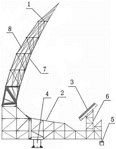
[0023] Such as figure 1 As shown, a large-scale high-precision parabolic offset feed antenna includes an antenna body 1, a feed array support 2, a feed array 3, a turntable 4 and a counterweight basket 5, and the antenna body 1 is arranged at one end of the feed array support 2. The other end of the feed array bracket 2 is provided with at least one transition bracket installation surface, the transition bracket 6 is installed on the transition bracket installation surface, the feed array 3 is respectively installed on the top of the transition bracket 6, and the turntable 4 is arranged on the feed array bracket 2 The counterweight basket 5 is connected to the end of the feed array support 2 close to the feed array 3 .

[0024] The antenna...


PUM


Abstract

The invention discloses a large-scale high-accuracy parabolic offset antenna which comprises an antenna body (1), a feed source array bracket (2), feed source arrays (3), a rotary table (4) and a counter weight device (5). The antenna body (1) is arranged at one end of the feed source array bracket (2); the other end of the feed source array bracket (2) is provided with at least one transition bracket mounting surface; the feed source arrays (3) are respectively arranged at the top ends of transition brackets (6); the rotary table (4) is arranged at the bottom of the feed source array bracket (2); and the counter weight device (5) is connected at the end of the feed source array bracket (2), which is close to the feed source arrays (3). According to the invention, a profile attachment technology is adopted and the manufacturing cost is reduced; a profile is riveted and cured and the problems of complex structure and control for the integral weight of a large-scale antenna are solved; a reflector skeleton adopts a truss structure, the feed source array bracket adopts a truss and thin shell beam mixed structure, and the structure design under a heavy load and under the complex boundary conditions of low weight, high stiffness requirement and the like is implemented.

Description

technical field [0001] The invention relates to a large-scale high-precision paraboloid bias feed antenna. Background technique [0002] The offset antenna is relative to the positive feed antenna, which means that the installation position of the feed source and the tuner of the offset antenna is not on a straight line perpendicular to the central section of the antenna and passing through the center of the antenna. The feed source of the forward-fed parabolic antenna is located in the main beam of the antenna, thus blocking the received electric wave, reducing the gain of the antenna and increasing the side lobe. Moving the feed source out of the aperture of the antenna reflector can eliminate the shielding of the feed source and its support for electromagnetic waves. Therefore, there is no effect of the so-called feed shadow. Under the premise of the same antenna area, processing accuracy, and receiving frequency, the gain of the offset antenna is greater than that of th...

Claims


Application Information

Patent Timeline
IPC IPC(8): H01Q1/12H01Q15/16H01Q19/17H01Q21/00
Inventor 张休玉王云飞靳广成邵昆林李明全
Owner CHENGDU JINJIANG ELECTRONICS SYST ENG
Learn More