
Flexible circuit board and structure of bend section of flexible circuit board

A flexible circuit board, bending part technology, applied in the directions of printed circuit components, printed circuits, printed circuits, etc., can solve the problems of flexible circuit board design constraints, and achieve the effects of high durability, excellent durability, and excellent flexibility

Active Publication Date: 2012-11-14
NIPPON STEEL CHEM &MATERIAL CO LTD
View PDF12 Cites 8 Cited by
  • Summary
  • Abstract
  • Description
  • Claims
  • Application Information

AI Technical Summary

Problems solved by technology

However, in these methods, the design of the flexible circuit board will be constrained

Method used


Image

  • Flexible circuit board and structure of bend section of flexible circuit board
  • Flexible circuit board and structure of bend section of flexible circuit board
  • Flexible circuit board and structure of bend section of flexible circuit board

Examples


Embodiment

[0082] Hereinafter, the present invention will be described more specifically based on Examples and Comparative Examples. In addition, the kind of copper foil used in Examples etc. and the synthesis|combination of a polyimide-acid solution are as follows.

[0083] [copper foil A]

[0084] Commercially available rolled copper foil with a purity of 99.9% and a thickness of 9 μm.

[0085] [copper foil B]

[0086] Commercially available electrolytic copper foil with a purity of 99.9% and a thickness of 9 μm.

[0087] [copper foil C]

[0088] Oxygen-free copper foil, purity 99.99%, thickness 9μm, processing condition A.

[0089] Impurities (mass ppm) Oxygen: 2, Silver: 18, Phosphorus: 2.1, Sulfur: 4, Iron: 1.5

[0090] [copper foil D]

[0091] Refined copper foil, purity 99.999%, thickness 9μm, processing condition A.

[0092] Impurities (mass ppm) Oxygen: 2, Silver: 5, Phosphorus: 0.01, Sulfur: 0.01, Iron: 0.002

[0093] [copper foil E]

[0094] Refined copper foil, purit...

Synthetic example 1)

[0108] N,N-Dimethylacetamide was charged into a reaction vessel capable of introducing nitrogen gas while being equipped with a thermocouple and a stirrer. In this reaction container, 2,2-bis[(4-(4 aminophenoxy)phenyl)]propane (BAPP) was dissolved in the container while stirring. Next, add pyromellitic anhydride (PMDA). The total amount of monomers charged was 15% by weight. Afterwards, the stirring was continued for 3 hours to obtain a resin solution of polyimide acid a. The solution viscosity of the resin solution of this polyimide-acid a was 3,000 cps.

Synthetic example 2)

[0110] N,N-Dimethylacetamide was charged into a reaction vessel capable of introducing nitrogen gas while being equipped with a thermocouple and a stirrer. 2,2'-Dimethyl-4,4'-diaminobiphenyl (m-TB) was put into this reaction container. Next, add 3,3’,4,4’-biphenyltetraic anhydride (BPDA) and pyromellitic anhydride (PMDA). The total amount of monomers charged was 15 wt%, and the molar (mol) ratio (BPDA:PMDA) of each acid anhydride was charged so that it was 20:80. Thereafter, stirring was continued for 3 hours to obtain a resin solution of polyimide b. The solution viscosity of the resin solution of this polyimide-acid b was 20,000 cps.


PUM

PropertyMeasurementUnit
diameteraaaaaaaaaa
thicknessaaaaaaaaaa
widthaaaaaaaaaa

Abstract

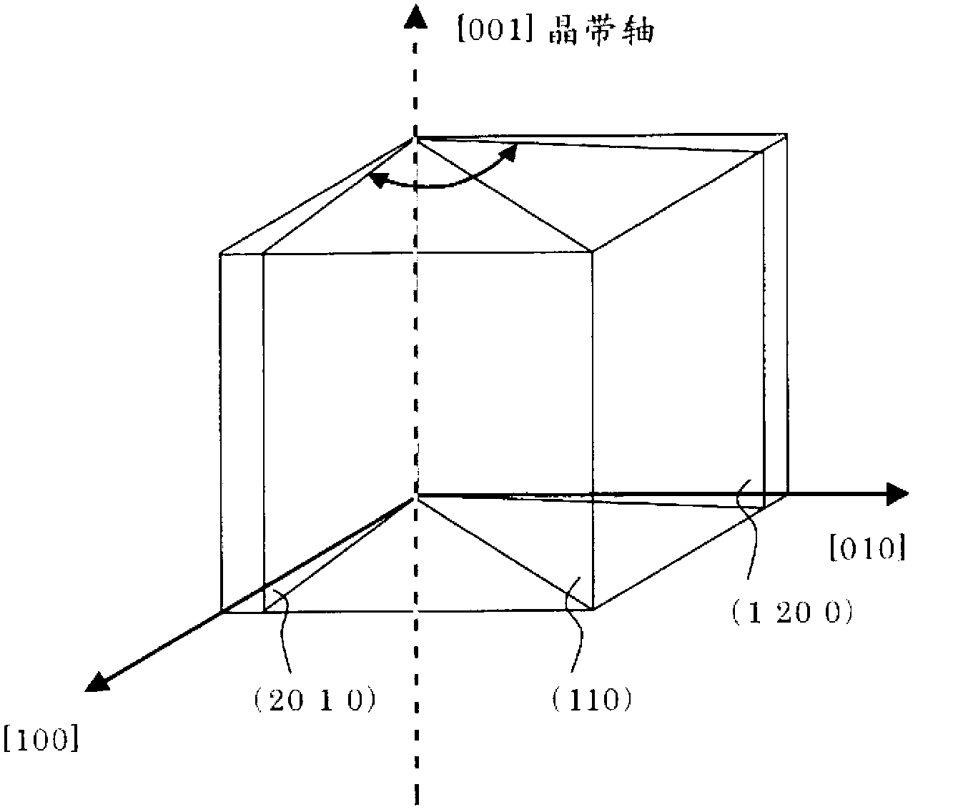
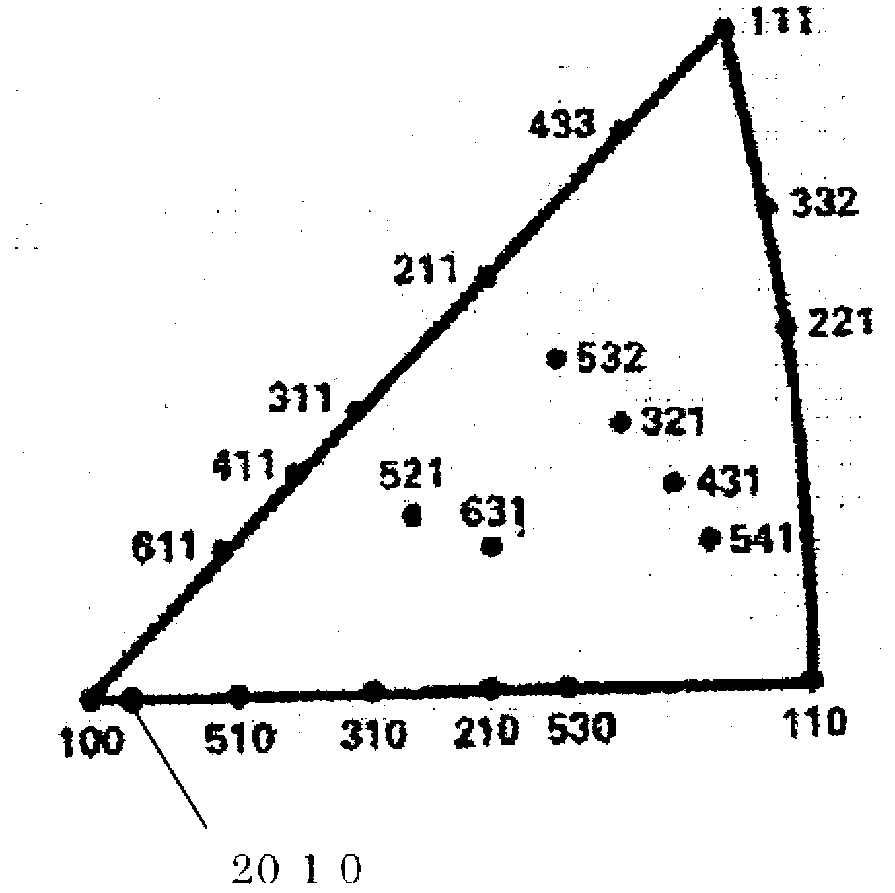
Disclosed is a flexible circuit board which has a bend section subjected to repeated bending and straightening with a small radius of curvature under severe conditions and which yet has durability and excellent flexibility. Specifically, the flexible circuit board is provided with a resin layer and wiring formed of metal foil and has a bend section in at least one portion of the wiring, wherein the metal foil is made of a metal having a face-centered cubic structure, wherein the preferred orientation region, in which the fundamental crystal axis <100> of each unit lattice of the face-centered cubic structure is within 10 DEG of perpendicular to the thickness direction of the metal foil and to a direction along the surface of the foil, occupies an area of 50% or more of the area of the board, and wherein the breaking elongation of the metal foil in a direction tangent to a cross-section (P) of the wiring taken along a plane extending from the ridge line of the bend section in the thickness direction of the metal foil is 3.5% or more and 20% or less.

Description

technical field [0001] The present invention relates to a flexible printed circuit board used with a bent portion at any position, and a bent portion structure of the flexible printed circuit board, and more specifically, to a flexible printed circuit board and a flexible printed circuit board that are durable against bending and excellent in bendability The structure of the curved part. Background technique [0002] Since a flexible circuit board (flexible printed circuit board) having a resin layer and wiring made of metal foil can be bent and used, it is used in movable parts in hard disks, hinge parts or slider sliding parts of mobile phones, printers, etc. It is widely used in various electronic and electrical equipment represented by the printing head of the printer, the optical pickup unit, and the movable part of the notebook PC. In addition, in recent years, in particular, along with the miniaturization, thinning, and high performance of these devices, it is requir...

Claims


Application Information

Patent Timeline
Patent Type & Authority Applications(China)
IPC IPC(8): C22F1/08H05K1/09B21B3/00C22F1/00
CPCH05K1/09C22C9/00H05K1/0393C22F1/08H05K2201/0355H05K1/028
Inventor 服部公一木村圭一
Owner NIPPON STEEL CHEM &MATERIAL CO LTD
Learn More