Plate type heat exchanger
A plate heat exchanger and plate technology, applied in the direction of heat exchanger types, indirect heat exchangers, heat exchange equipment, etc., can solve problems such as changing the heat transfer area, improve heat capacity, avoid a substantial increase in power, increase The effect of effective heat exchange area
- Summary
- Abstract
- Description
- Claims
- Application Information
AI Technical Summary
Problems solved by technology
Method used
Image
Examples
Embodiment 1
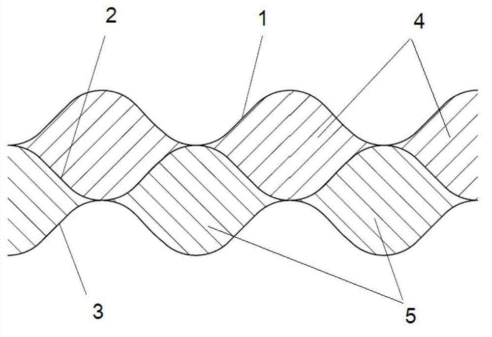
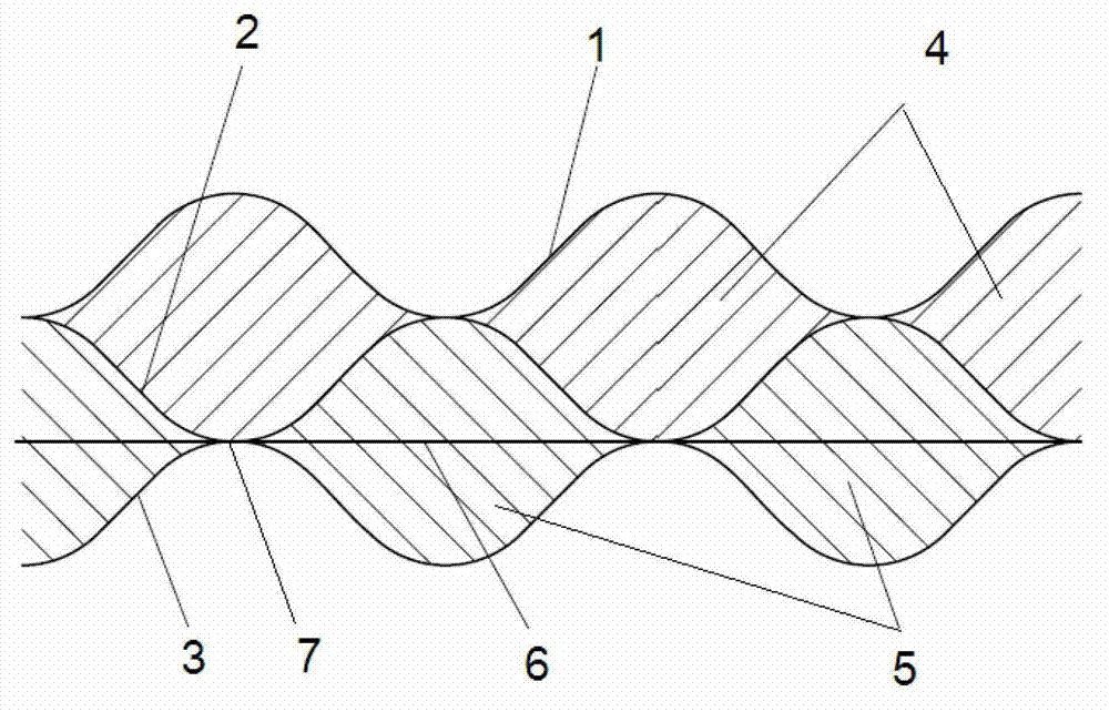
[0032] Specific reference attached image 3 It can be seen that the plate heat exchanger constructed according to a preferred embodiment of the present invention is a high-efficiency heat exchanger formed by stacking a series of plates with a certain corrugated shape. exist image 3 Only three plates are shown in , namely the first plate 1 , the second plate 2 and the third plate 3 . The first flow channel 4 is formed between the first plate 1 and the second plate 2, and the second flow channel 5 is formed between the second plate 2 and the third plate 3 to separate the hot and cold fluids so that the hot and cold fluids Flow in the flow channels 4 and 5 on both sides of the second plate 2 respectively, and exchange heat through the second plate 2 .
[0033] A straight screen 6 is arranged in the second channel 5 to form a reinforcing sheet.
[0034] In this embodiment, the second sheet 2 and the flat screen 6 , and the third sheet 3 and the flat screen 6 have intimate cont...
Embodiment 2
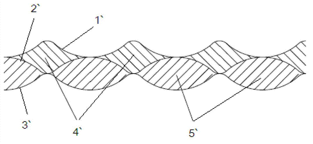
[0038] Specific reference attached Figure 4 It can be seen that the plate heat exchanger constructed according to a preferred embodiment of the present invention is a high-efficiency heat exchanger formed by stacking a series of plates with a certain corrugated shape. exist Figure 4Only three plates are shown in , namely the first plate 1 , the second plate 2 and the third plate 3 . The first flow channel 4 is formed between the first plate 1 and the second plate 2, and the second flow channel 5 is formed between the second plate 2 and the third plate 3 to separate the cold and hot fluids, making them respectively The flow channels 4 and 5 on both sides of the second plate 2 flow through the second plate 2 or the third plate 3 to exchange heat between the hot and cold fluids.
[0039] The plate heat exchanger constructed according to this embodiment includes a first perforated plate 61 , a second perforated plate 62 , a third perforated plate 63 and a fourth perforated pla...
Embodiment 3
[0047] Specific reference attached Figure 5 It can be seen that the plate heat exchanger constructed according to a preferred embodiment of the present invention is a high-efficiency heat exchanger formed by stacking a series of plates with a certain corrugated shape. exist Figure 4 Only three plates are shown in , namely the first plate 1 , the second plate 2 and the third plate 3 . The first flow channel 4 is formed between the first plate 1 and the second plate 2, and the second flow channel 5 is formed between the second plate 2 and the third plate 3 to separate the cold and hot fluids, making them respectively The flow channels 4 and 5 on both sides of the second plate 2 flow through the second plate 2 to exchange heat between the hot and cold fluids.
[0048] The plate heat exchanger constructed according to this embodiment includes first, second, and third perforated plates 61 ′, 62 ′, 63 ′ as reinforcing sheets.
[0049] First, second and third perforated plates 6...
PUM
 Abstract
Description
Claims
Application Information
 - R&D
- Intellectual Property
- Life Sciences
- Materials
- Tech Scout
- Unparalleled Data Quality
- Higher Quality Content
- 60% Fewer Hallucinations
Browse by: Latest US Patents, China's latest patents, Technical Efficacy Thesaurus, Application Domain, Technology Topic, Popular Technical Reports.
© 2025 PatSnap. All rights reserved.Legal|Privacy policy|Modern Slavery Act Transparency Statement|Sitemap|About US| Contact US: help@patsnap.com


