
Positive electrode current collector for lithium ion secondary battery, positive electrode for lithium ion secondary battery, and process for production of positive electrode current collector for lithium ion secondary battery

A technology for positive electrode current collectors and secondary batteries, applied in secondary batteries, electrode carriers/current collectors, battery electrodes, etc., can solve the problems of reduced battery life, poor adhesion, peeling, etc., and achieve improved battery life, easy and The effect of reliable production and improvement of adhesion

Inactive Publication Date: 2012-10-31
KOBE STEEL LTD
View PDF6 Cites 3 Cited by
  • Summary
  • Abstract
  • Description
  • Claims
  • Application Information

AI Technical Summary

Problems solved by technology

Moreover, such an oxide film is generally poor in adhesion to carbon (C), so even if a carbon intermediate film is formed on the surface of the current collector as in the inventions of Patent Document 1 and Patent Document 2, the carbon (C) film will still occur along with charging and discharging. The problem of peeling off the carbon interlayer from the current collector
In addition, if the carbon intermediate film is peeled off from the current collector in this way, the active material layer covered on it is also peeled off at the same time, so it also becomes a factor of reduced battery life.
Therefore, the inventions of Patent Document 1 and Patent Document 2 cannot improve the adhesion of the interface between the current collector and the active material layer.

Method used

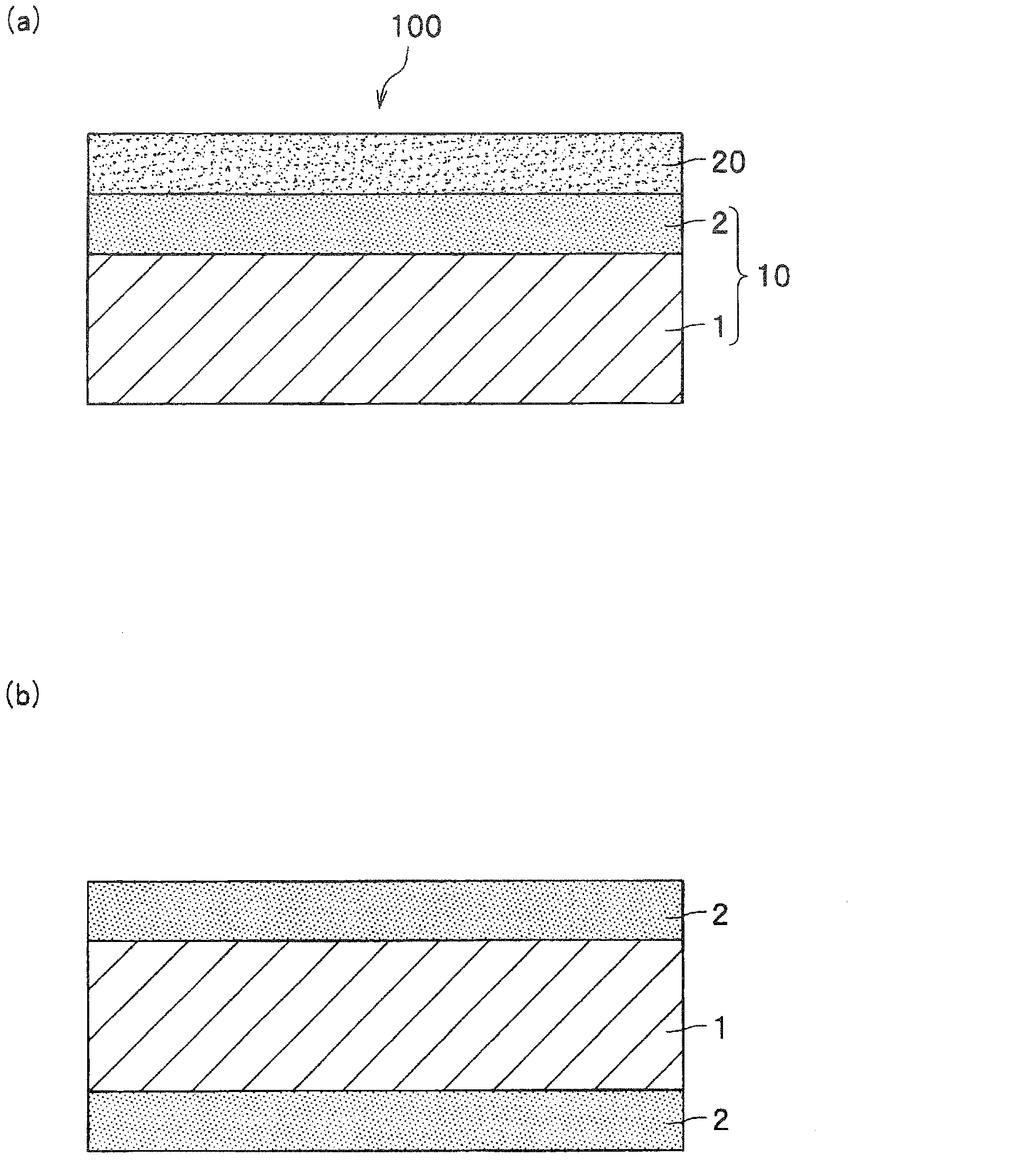
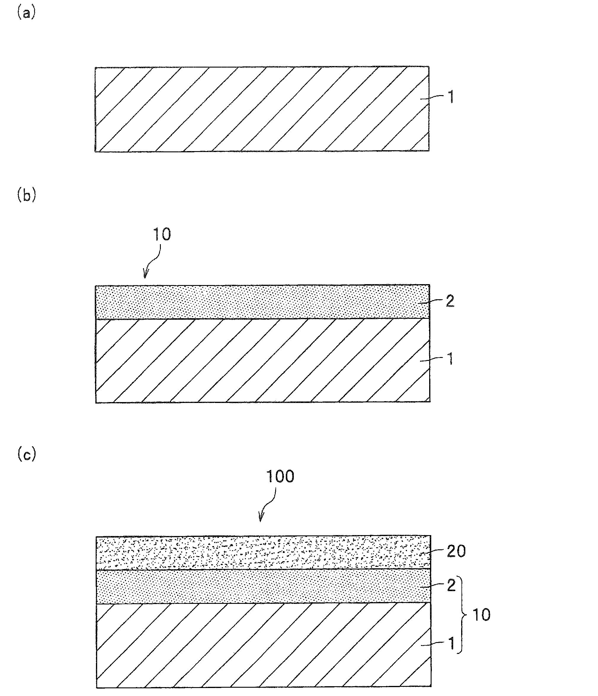

Image

  • Positive electrode current collector for lithium ion secondary battery, positive electrode for lithium ion secondary battery, and process for production of positive electrode current collector for lithium ion secondary battery
  • Positive electrode current collector for lithium ion secondary battery, positive electrode for lithium ion secondary battery, and process for production of positive electrode current collector for lithium ion secondary battery
  • Positive electrode current collector for lithium ion secondary battery, positive electrode for lithium ion secondary battery, and process for production of positive electrode current collector for lithium ion secondary battery

Examples


no. 1 example

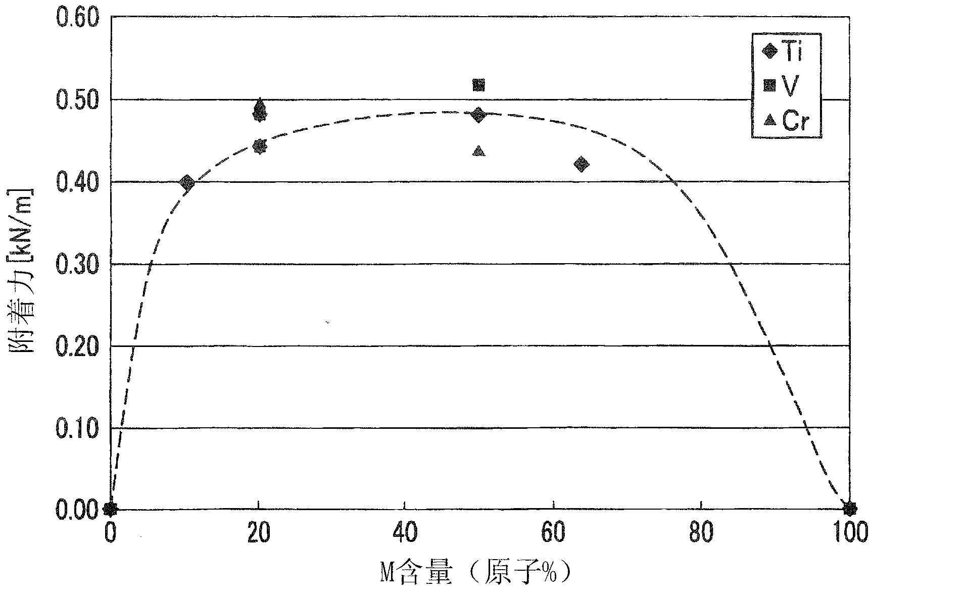
[0088] Next, the positive electrode that satisfies the requirements of the present invention and the positive electrode that does not meet the requirements of the present invention will be shown to compare the adhesion of the current collector and the positive electrode active material layer at the interface. First, the positive electrode used in this embodiment will be described along the manufacturing process. In addition, the comparative example 4 of this example is assumed to be a positive electrode in which an intermediate film of carbon is formed on a current collector made of a conductive material described in Patent Document 1.

[0089] (1) Aluminum foil manufacturing process

[0090] In the aluminum foil manufacturing process, the same treatment was performed in Examples 1 to 12 and Comparative Examples 1 to 10. That is, the aluminum plate was rolled to produce an aluminum foil having a length of 50 mm × a width of 50 mm × a thickness of 15 μm.

[0091] (2) Surface layer f...

no. 2 example

[0108] Next, in order to investigate more preferable forms of the current collector and the positive electrode of the present invention, an example for comparing the wettability of the surface of the current collector is shown. In addition, this characteristic is only a desirable characteristic of the present invention. Therefore, even if this characteristic is not satisfied and the adhesion of the first embodiment is satisfied, the minimum objective of the invention can be achieved. In this example, using Examples 1 to 12 and Comparative Examples 1 to 3, and 5 to 8 manufactured by the same manufacturing process as the aforementioned first example, the following measurement and evaluation were performed.

[0109] (1) Measurement of the composition of the surface layer

[0110] After the aforementioned surface layer formation process, the composition of the surface layer was measured by AES.

[0111] (2) Measurement and evaluation of water contact angle

[0112] After the aforemention...

no. 3 example

[0120] Next, in order to investigate more preferable forms of the current collector and the positive electrode of the present invention, an example with comparative corrosion resistance is shown. In addition, this characteristic is merely a desired characteristic of the present invention. Therefore, even if this characteristic is not satisfied and the adhesion of the first embodiment is satisfied, the minimum objective of the present invention can still be achieved. In this example, using Examples 3 to 5, 8, 9, and 13 and Comparative Examples 8 to 10 manufactured by the same manufacturing process as the aforementioned first example, the following treatment was performed.

[0121] (1) Measurement of the composition of the surface layer

[0122] After the aforementioned surface layer formation process, the composition of the surface layer was measured by AES.

[0123] (2) Evaluation of corrosion resistance

[0124] Using the positive electrode produced by the method described above, a ...


PUM

PropertyMeasurementUnit
Thicknessaaaaaaaaaa
Thicknessaaaaaaaaaa

Abstract

Disclosed is a positive electrode current collector for a lithium ion secondary battery, which is characterized by comprising an aluminum foil comprising pure aluminum or an aluminum alloy and a surface layer formed on one surface or both surfaces of the aluminum foil, wherein the surface layer contains C in an amount of 10 to 95 at.% and additionally contains at least one element selected from Group 4 to Group 6 elements in an amount of 5 to 90 at.%. Also disclosed is a positive electrode for a lithium ion secondary battery, which is characterized by having a positive electrode active material layer that covers the surface layer of the positive electrode current collector for a lithium ion secondary battery. It becomes possible to prevent the elution of the current collector into an electrolytic solution to improve the adhesion between the current collector and the active material in the interface therebetween and increase the service life of a battery.

Description

Technical field [0001] The present invention relates to a positive electrode current collector used in a lithium ion secondary battery, a positive electrode and a method for manufacturing the positive electrode current collector. Background technique [0002] In recent years, due to the miniaturization and high performance of mobile devices, the energy density (charge and discharge capacity) of the secondary batteries mounted on the mobile devices has been increasing. Among them, lithium-ion secondary batteries (hereinafter referred to as secondary batteries, as appropriate) are compared with nickel-cadmium secondary batteries and nickel-hydrogen secondary batteries, so they show higher voltage and higher energy density, so they are beginning to be widely used Used as a power source for mobile devices. In addition, with the increase in environmental awareness, it is expected to shift from cars using current fossil fuels to CO 2 As electric vehicles or hybrid vehicles with low em...

Claims


Application Information

Patent Timeline
IPC IPC(8): H01M4/66H01M4/70
CPCH01M10/0525H01M4/663Y02T10/7011H01M4/661H01M4/667Y02E60/10
Inventor 桂翔生佐藤俊树铃木顺细川护大西隆
Owner KOBE STEEL LTD
Learn More