
Friction plate milling machine

A friction plate and grinding machine technology, applied in the field of machinery, can solve the problems of product straightness, flatness, verticality and concentricity cannot be well guaranteed, low efficiency, etc. area effect

Inactive Publication Date: 2012-10-24
CHONGQING BISHAN HONGXIANG AUTO PARTS
View PDF6 Cites 2 Cited by
  • Summary
  • Abstract
  • Description
  • Claims
  • Application Information

AI Technical Summary

Problems solved by technology

[0002] At present, when the friction plate in the brake is grinding the outer circle, the grinding process of the friction plate perpendicular to the main shaft of the grinding disc is mostly used, so the straightness, flatness, verticality and concentricity of the ground product cannot be well guaranteed. With the continuous increase of new product types and the continuous improvement of product quality, the grinding process is also in urgent need of improvement; in addition, when loading and unloading parts, the operator needs to tighten the screws before grinding, and each time a single piece is cut and ground ,low efficiency

Method used


Image

  • Friction plate milling machine
  • Friction plate milling machine

Examples


Embodiment Construction

[0011] Below by embodiment, in conjunction with accompanying drawing, the present invention is described in further detail:

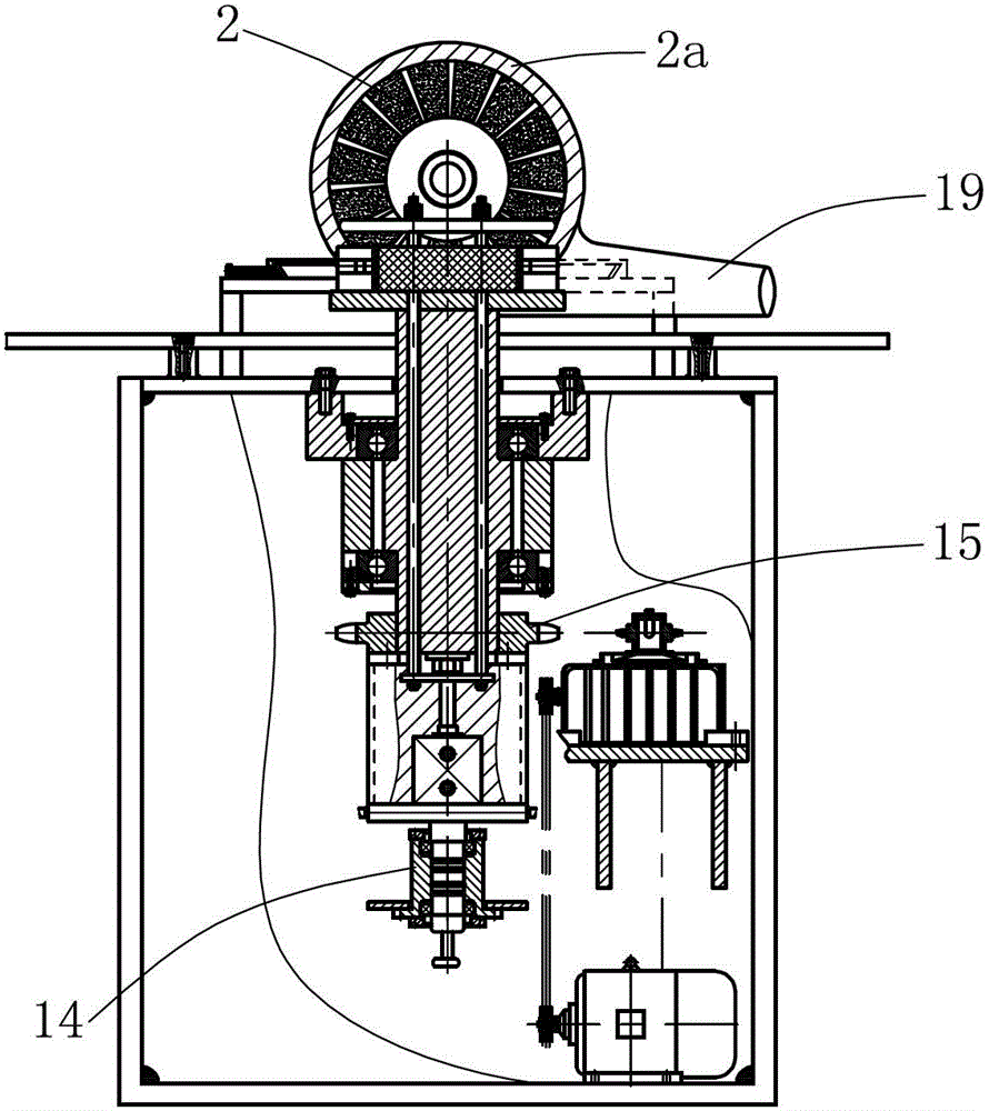
[0012] Such as figure 1 , figure 2 The friction disc grinding machine shown is mainly composed of frame assembly 1, grinding wheel 2, grinding wheel drive motor 3, "⊥" shaped round table 4, part positioning plate 5, part rotating spindle 6, screw rod 7, bearing seat 9, thin Cylinder 10, pneumatic pressure plate 11, parts pressing and connecting pull rod 12, pressure plate pneumatic reversing sensor contact 13, pressure plate pneumatic commutator 14, sprocket chain mechanism 15, worm gear and worm speed changer 16 and other components.

[0013] The grinding wheel 2 and the grinding wheel driving motor 3 are arranged above the frame assembly 1 , the axis of the grinding wheel 2 is arranged horizontally, and the grinding wheel driving motor 3 is positioned at the rear of the grinding wheel 2 . The front of the grinding wheel 2 is a workbench 1a, and the...


PUM


Abstract

The invention discloses a friction plate milling machine, which comprises a machine frame assembly, a grinding wheel, a grinding wheel driving motor, a reversed T-shaped round platform, a component positioning plate, a component rotating spindle, a bearing seat, a pressure plate pneumatic reversing induction contact, a pressure plate pneumatic reverser, a chain wheel and chain mechanism, a worm and gear variator and a spindle rotating machine; the upper part of the step surface of the reversed T-shaped round platform and the peripheral region of the component positioning plate form two circumferentially arranged friction plate accommodation spaces together; two thin cylinders are arranged below the component rotating spindle; a pneumatic pressure plate is arranged above each friction plate accommodation space correspondingly; each pneumatic pressure plate is correspondingly provided with two component compression connecting pull rods; and the lower ends of the two component compression connecting pull rods are connected with one of the two thin cylinders. The friction plate milling machine has good processing product quality and high milling efficiency, thereby guaranteeing the straightness accuracy, planarity, verticality and concentricity of friction plate better.

Description

technical field [0001] The invention relates to grinding equipment for friction plates in automobile brakes, belonging to the field of machinery. Background technique [0002] At present, when the friction plate in the brake is grinding the outer circle, the grinding process of the friction plate perpendicular to the main shaft of the grinding disc is mostly used, so the straightness, flatness, verticality and concentricity of the ground product cannot be well guaranteed. With the continuous increase of new product types and the continuous improvement of product quality, the grinding process is also in urgent need of improvement; in addition, when loading and unloading parts, the operator needs to tighten the screws before grinding, and each time a single piece is cut and ground ,low efficiency. Contents of the invention [0003] The purpose of the present invention is to provide a friction plate grinding machine with good quality of processed products and high grinding e...

Claims


Application Information

Patent Timeline
IPC IPC(8): B24B5/36B24B55/06
Inventor 敖良均田洪相陈少元
Owner CHONGQING BISHAN HONGXIANG AUTO PARTS
Learn More