Ultrasonic vibration aided stir friction welding process and device

An ultrasonic vibration and auxiliary stirring technology, applied in welding equipment, manufacturing tools, non-electric welding equipment, etc., can solve the problems of hindering the ultrasonic vibration of stirring needles, complicated system fabrication, and large equipment changes, so as to improve welding quality and expand the scope of application. , the effect of reducing requirements

Active Publication Date: 2015-06-03
SHANDONG UNIV
View PDF4 Cites 2 Cited by
  • Summary
  • Abstract
  • Description
  • Claims
  • Application Information

AI Technical Summary

Problems solved by technology

However, with this design, the downward pressure during welding seriously hinders the ultrasonic vibration of the stirring needle, and the equipment of the original friction stir welding machine has been greatly changed, the system is complicated to manufacture, and the ultrasonic vibration system must reach a resonance state with the stirring needle, so for For workpieces with different thicknesses, the matching ultrasonic vibration system needs to be replaced when the stirring needle is replaced, which has poor adaptability

Method used


Image

  • Ultrasonic vibration aided stir friction welding process and device
  • Ultrasonic vibration aided stir friction welding process and device
  • Ultrasonic vibration aided stir friction welding process and device

Examples


Embodiment 1

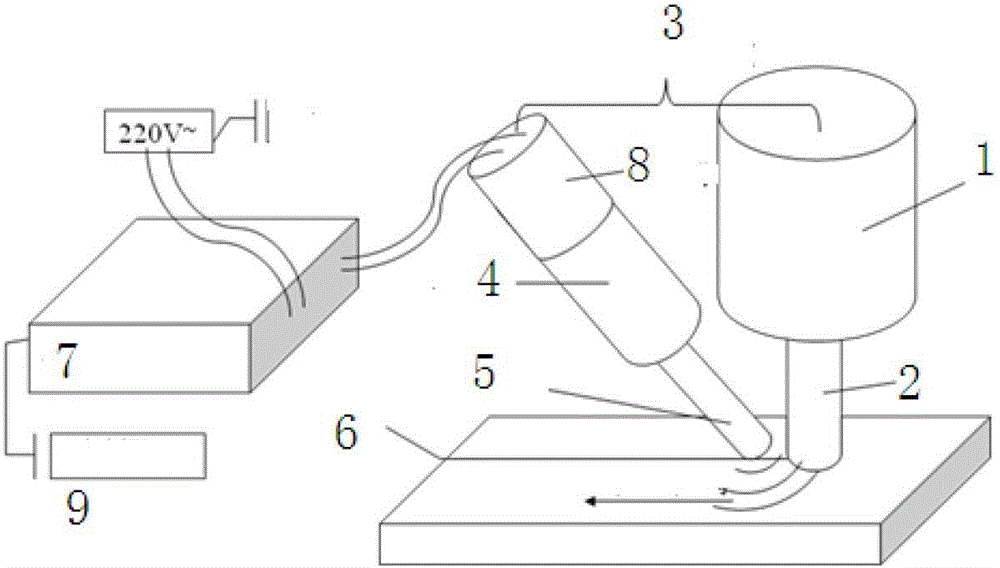
[0037] Ultrasonic vibration assisted friction stir welding device, including friction stir welding machine 1 with stirring head 2, ultrasonic generator 7, transducer 8, horn 4, tool head 5, ultrasonic generator 7 is connected to the vibration unit through a signal transmission line, The vibration unit includes a transducer 8, a horn 4, and a tool head 5. The transducer is connected to the horn, and the horn is connected to the tool head. Both are connected by studs. The ultrasonic vibration of the tool head The introduction point is in the area to be welded in front of the stirring head, and the vibration unit is fixed with the friction stir welding machine 1 through the positioning fixture 3 .

[0038]The positioning fixture includes a cuboid frame 10, a connecting piece 11, and a cylindrical fixture 12. The cuboid frame 10 includes a front splint 13 and a rear splint 14. Between the front splint 13 and the rear splint 14 is an upper baffle plate 20 of the friction stir weldin...

Embodiment 2

[0043] The ultrasonic vibration assisted friction stir welding device includes a friction stir welding machine 1 with a stirring head 2, an ultrasonic generator 7, a transducer 8, and a vibration unit. The ultrasonic generator 7 is connected to the vibration unit through the transducer 8. The vibration unit includes a transformer The horn 4 and the horn 4 are connected to the tool head 5. The ultrasonic vibration introduction point of the tool head 5 is in the area to be welded in front of the stirring head. The vibration unit is fixed with the friction stir welding machine 1 through the positioning fixture 3.

[0044] The positioning fixture includes a cuboid frame 10, a leading screw, and a cylindrical fixture 12. The cuboid frame 10 includes a front splint 13 and a rear splint 14. Between the front splint 13 and the rear splint 14 is a friction stir welding machine 1 upper baffle plate 20, The front and rear splints are tightly matched with the upper baffle plate of the fric...


PUM


Abstract

The invention relates to an ultrasonic vibration aided stir friction welding process and a device. Power frequency alternating current is transformed into ultrasonic high frequency alternating current signals through an ultrasonic generator. Electric energy is transformed into ultrasonic mechanical vibration energy through a transducer. After the amplitude is further amplified through a variable amplitude bar, ultrasonic waves are conducted into materials through a toolhead from the welding areas around a stirring head for welding through the stirring head in a welding direction. Compared with the method that the variable amplitude bar of an ultrasonic transducer is coupled with the stirring head, after a system is integrated by utilizing a self designed positioning clamping appliance, the stability of a vibration system is efficiently guaranteed, two-dimensional adjustment in upper, lower, front and back directions is realized, and the distance between the toolhead and the stirring head is easily adjusted, so that the ultrasonic vibration aided stir friction welding process and the device are suitable for stirring heads with different specifications and have the advantage of wide adaptability.

Description

technical field [0001] The invention relates to a material connection method, in particular to an ultrasonic vibration-assisted friction stir welding process and device. Background technique [0002] Friction stir welding (FSW for short) is a solid-phase joining technology invented by the British Welding Institute in 1991. It has the advantages of small welding deformation, high welding quality, green and pollution-free, and is called "the most revolutionary in the 21st century. Sexual connection technology". However, due to the huge axial downward pressure and horizontal shear force on the stirring head during the welding process, its welding speed is limited, and the stirring head is severely worn, which also puts forward high requirements for friction stir welding equipment and fixtures. Scholars at home and abroad improve the welding environment by using additional auxiliary heat sources such as mobile induction coils, resistance heating, laser energy or plasma arcs, bu...

Claims


Application Information

Patent Timeline
Patent Type & Authority Patents(China)
IPC IPC(8): B23K20/12B23K20/26
Inventor 武传松刘小超张皓庭
Owner SHANDONG UNIV
Why Eureka
Try Eureka