
Hydraulic shock absorber

A shock absorber, hydraulic technology, used in shock absorbers, shock absorbers, springs/shock absorbers, etc., can solve problems such as reduced sealing, reduced oil outflow, and reduced buffer capacity, and achieves good sliding properties , The effect of improving durability and prolonging life

Inactive Publication Date: 2012-10-17
SMC CORP
View PDF6 Cites 3 Cited by
  • Summary
  • Abstract
  • Description
  • Claims
  • Application Information

AI Technical Summary

Problems solved by technology

[0005] However, since the above-mentioned oil film also functions as a lubricating oil used for the sliding of the piston rod seal provided on the end wall of the piston rod side and the above-mentioned piston rod on the other hand, if the oil film is removed too much, The sliding resistance of the piston rod increases, the sliding characteristics deteriorate, and the above-mentioned piston rod seal wears and the sealing performance decreases
[0006] Therefore, it has to be configured so that a necessary amount of oil flows out as lubricating oil, and there is a limit to reducing the outflow of oil.
Moreover, this situation is the biggest bottleneck in preventing the shock absorber from reducing the cushioning capacity of the shock absorber due to the reduction in oil volume.

Method used


Image

  • Hydraulic shock absorber
  • Hydraulic shock absorber
  • Hydraulic shock absorber

Examples


Embodiment Construction

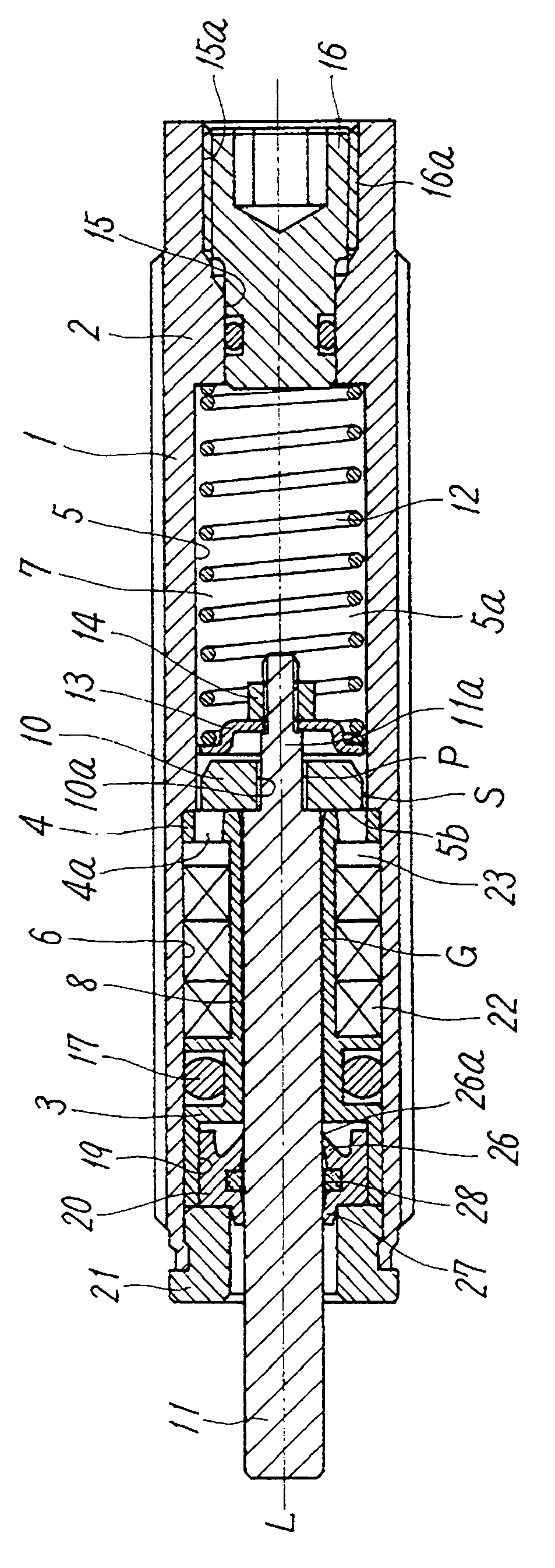
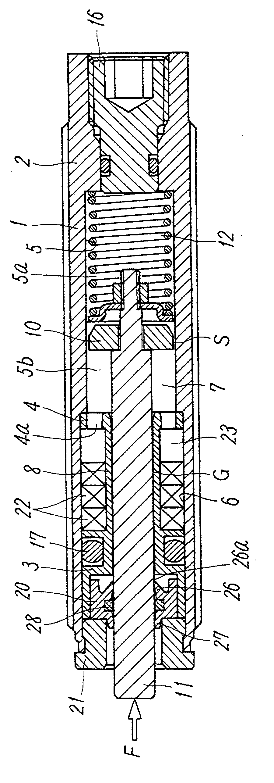
[0024] Figure 1-Figure 3 It is a figure which shows the 1st Embodiment of the hydraulic shock absorber of this invention. This shock absorber has a cylindrical cylinder housing 1 . The cylinder housing 1 has a cover-side end wall 2 located on the base end side in the axis L direction, a piston rod-side end wall 3 located on the front end side, and an intermediate wall 4 located in between. A piston chamber 5 is formed between the two, and an accumulator chamber 6 is formed between the intermediate wall 4 and the rod-side end wall 3, and the piston chamber 5 and the accumulator chamber 6 are filled with oil 7 in a pressurized state. The piston chamber 5 and the accumulator chamber 6 communicate with each other through the communication hole 4 a of the intermediate wall 4 .

[0025] A buffer piston 10 having a smaller outer diameter than the inner diameter of the piston chamber 5 is mounted on the cylinder housing 1 in a state where a gap S through which the oil 7 flows is ma...


PUM


Abstract

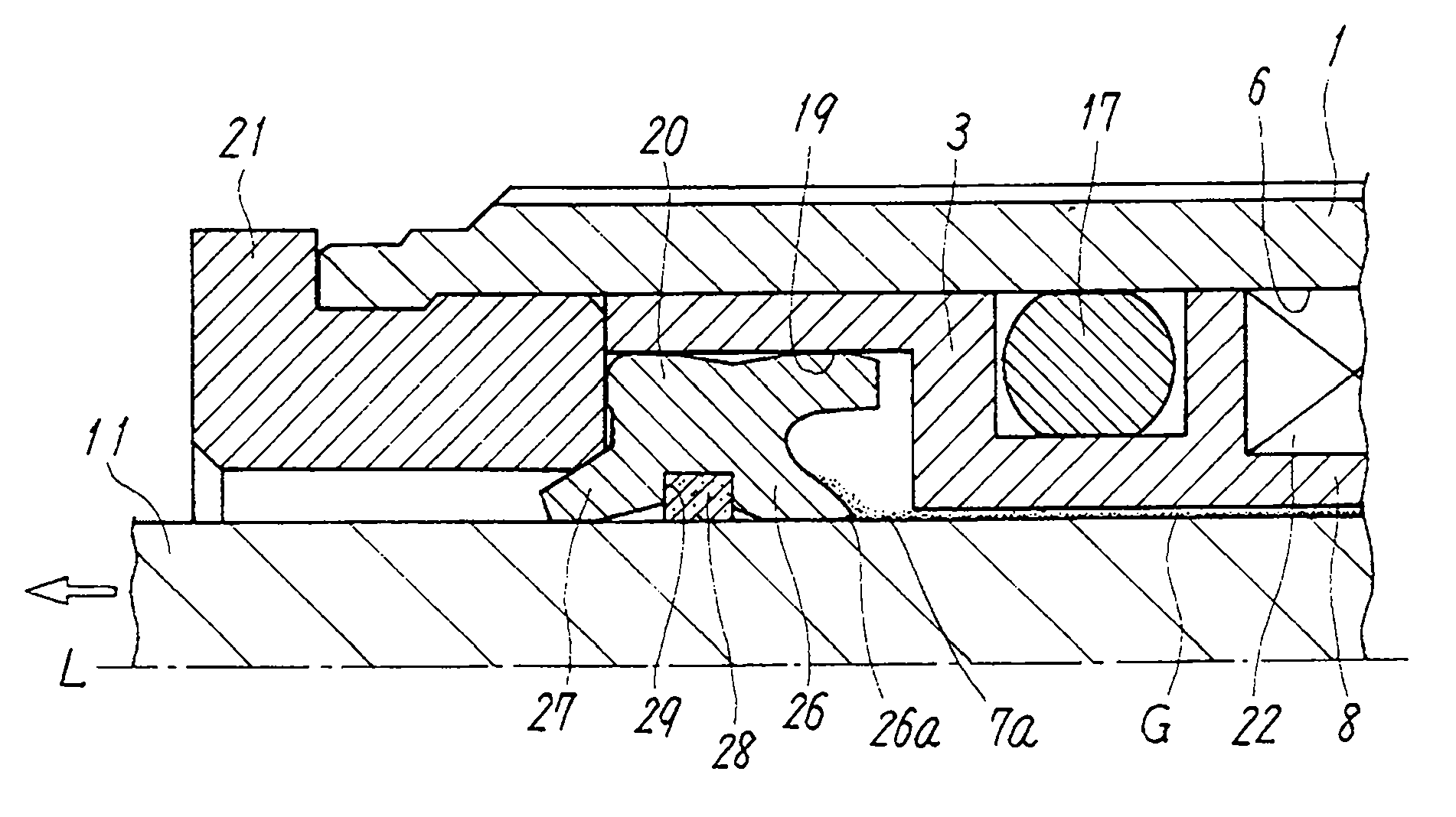
Provided is a hydraulic shock absorber such that an oil film stuck to the outer periphery of a rod is removed to the utmost, resulting in the oil outflow amount being reduced, and that at the same time, it is made possible to secure satisfactory slidability between said rod and a rod gasket and to prevent wear of said rod gasket. A first lip (26) for scraping off the oil film (7a) which is stuck to the outer periphery of the rod (11) is formed in the rod gasket (20), which is interposed between the outer periphery of the rod (11) and the inner periphery of a rod side end wall (3). Furthermore, a ring-shaped grease retaining member (28) which supplies retained grease to the outer periphery of the rod (11) is provided. Said grease retaining member (28) is made to contact the outer periphery of the rod (11) at a position nearer the rod tip than is the first lip (26).

Description

technical field [0001] The present invention relates to a hydraulic shock absorber for buffering the shock when a moving object is stopped by utilizing the flow resistance of oil. Background technique [0002] For example, as described in Patent Document 1, a hydraulic shock absorber has a structure in which oil such as mineral oil is filled in a piston chamber of a cylinder housing, and a piston for braking is accommodated in a state where the oil circulation gap is maintained. On the outer periphery, the piston rod connected to the piston slidably penetrates the piston rod-side end wall (sleeve) of the cylinder housing and extends to the outside. Then, when a moving object collides with the tip of the piston rod to displace the piston, the kinetic energy of the moving object is absorbed by the flow resistance of the oil flowing through the communication gap. [0003] The above-mentioned piston rod repeats the urging force generated by the return spring, usually occupies t...

Claims


Application Information

Patent Timeline
Patent Type & Authority Applications(China)
IPC IPC(8): F16F9/36F16J15/32F16J15/447F16J15/3232F16J15/324
CPCF16F9/363F16F9/36F16J15/32F16J15/447
Inventor 宫里英考广木章金子纯也高桑洋二门田谦吾石川真之结束茉利子
Owner SMC CORP
Learn More