
Power converting device

A power conversion device and power consumption technology, which is applied in the direction of converting irreversible DC power input into AC power output, controlling electromechanical transmission devices, and AC motor deceleration devices, etc., can solve the problem of increasing motor power consumption, increasing motor loss, and consumption And other issues

Inactive Publication Date: 2012-10-17
HITACHI IND EQUIP SYST CO LTD
View PDF5 Cites 7 Cited by
  • Summary
  • Abstract
  • Description
  • Claims
  • Application Information

AI Technical Summary

Problems solved by technology

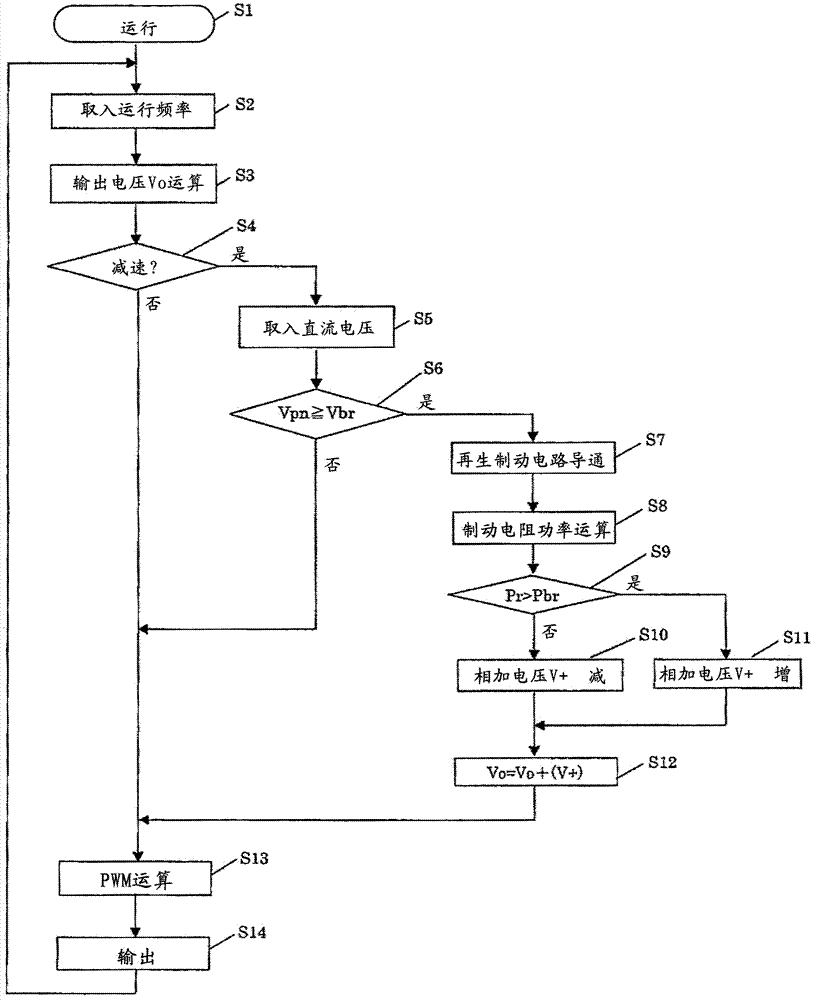
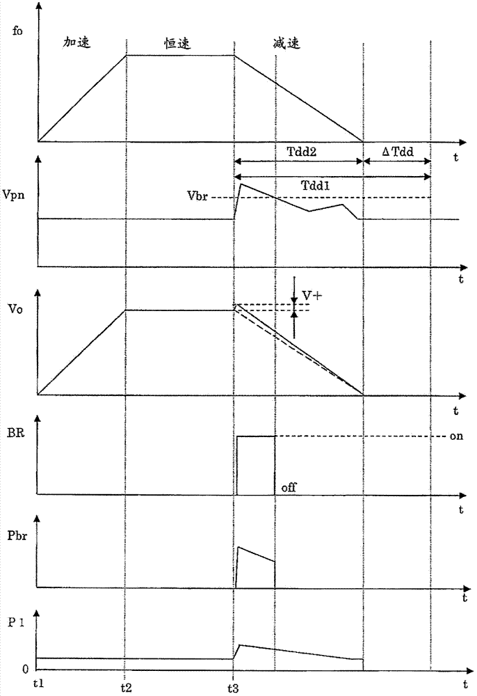
[0004] In the above-mentioned Patent Document 1 or Patent Document 2, there is a problem that the output voltage is increased regardless of the allowable power capacity of the connected regenerative braking resistor, and the power consumption of the motor is increased. There is a margin in the motor and the loss in the motor is increased without preparation, or on the contrary, the resistor consumes more than the allowable power capacity of the regenerative braking resistor.

Method used


Image

  • Power converting device
  • Power converting device
  • Power converting device

Examples


Embodiment 1

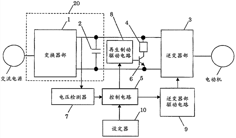
[0019] figure 1 is a structural diagram of this embodiment. The AC power is rectified by the inverter unit 1 and the capacitor 2 to convert it into a DC voltage. The inverter unit 3 converts the DC voltage into a required AC voltage and outputs it to the motor. The transistor 6 functions as a switch for operating the regenerative braking resistor 4 . According to the regenerative operation state during the deceleration operation of the motor, conduction operation is performed when the inverter regenerates energy, and the regenerated energy is consumed as heat by the regenerative braking resistor 4 .

[0020] The voltage detector 7 constantly monitors the voltage of the DC unit 20 and sends a DC voltage signal Vpn to the control circuit 5 . The setting device 10 is a device for performing various settings such as the output frequency of the inverter, and sends various set values ​​to the control circuit 5 . The MCU (not shown) installed in the control circuit 5 performs var...

Embodiment 2

[0068] If the value for increasing the output voltage is too large, the heat generation of the motor will further increase, and the motor itself may burn out. Therefore, it is necessary to set limits on the added voltage V+ according to the characteristics of the motor.

[0069] In Embodiment 1, when the amount of regeneration is large and the output voltage Vo reaches the limit value, the regenerative power cannot be completely consumed in the regenerative braking resistor 4, the voltage Vpn of the DC part 20 rises, and finally the overvoltage protection is implemented, resulting in The inverter stops.

[0070] A temperature sensor is generally built into the regenerative braking resistor 4. When the excessive regeneration amount is consumed as heat, the temperature of the resistor element rises sharply, and the temperature sensor operates to protect the regenerative braking resistor 4. The transistor 6 is stopped for the purpose of preventing abnormal heat release. Therefo...


PUM


Abstract

The present invention provides a power converting device that enables effective use of an allowable power capacity of a connected regenerative braking resistor that is previously set, by automatically adjusting an output voltage and deceleration time according to the power capacity. A voltage-type power converting device that controls driving of an induction motor, the voltage-type power converting device including a regenerated power consumption circuit and a regenerative braking resistor, wherein an allowable power capacity of the connected regenerative braking resistor and its resistance are previously set for the power converting device, and a voltage output to a motor at a time of deceleration is changed according to the allowable power capacity and its resistance.

Description

technical field [0001] The present invention relates to a voltage-type power conversion device for driving and controlling a motor, and to a control method when the motor is decelerated. Background technique [0002] As background art in this technical field, there are Japanese Patent Laid-Open No. 7-7981 (Patent Document 1) and Japanese Patent Laid-Open No. 7-267525 (Patent Document 2). In this gazette, it is described that "by reducing or eliminating the capacity of the braking resistor and the like provided in the DC intermediate circuit of the voltage-type power conversion device for driving an induction motor, the power conversion device can be made small and inexpensive. The regenerative power detector for detecting the regenerative power from the induction motor absorbed by the capacitor via the inverter part is provided, and the detection signal of the detector is applied to the function generator in the inverter control circuit, and the The above-mentioned function...

Claims


Application Information

Patent Timeline
Patent Type & Authority Applications(China)
IPC IPC(8): H02P3/22H02M7/48H02P21/36H02P23/07H02P25/04H02P27/06H02P27/08
CPCH02P3/22H02P29/024H02P29/0241H02P2207/01
Inventor 高田直树井堀敏
Owner HITACHI IND EQUIP SYST CO LTD
Learn More