Eureka AIR delivers breakthrough ideas for toughest innovation challenges, trusted by R&D personnel around the world.

Wavefront measuring method based on Hartmann wavefront sensor

A wavefront measurement and sensor technology, applied in the field of optical information measurement, can solve problems such as limitations, complex manufacturing process, and difficulty in realization, and achieve the effects of improving precision, high utilization of light energy, and improving wavefront measurement accuracy

Active Publication Date: 2012-10-17
INST OF OPTICS & ELECTRONICS - CHINESE ACAD OF SCI
View PDF5 Cites 48 Cited by
  • Summary
  • Abstract
  • Description
  • Claims
  • Application Information

AI Technical Summary

Problems solved by technology

The above-mentioned methods for improving the measurement accuracy of the Hartmann wavefront sensor regard the wavefront in each sub-aperture as a first-order plane containing only oblique aberrations. This premise limits the space for further improvement of the accuracy of the Hartmann wavefront sensor. Its application in high precision measurement
[0004] Shane Barwick proposed using an astigmatic hybrid wavefront sensor to simultaneously measure the first-order slope and quadratic curvature of the sub-aperture wavefront, see "Detecting higher-order wavefront errors with an astigmatic hybrid wavefront sensor" [Shane Barwick.[J]. OPTICS LETTERS, 2009, 34(11)], this method requires each lens in the microlens to retain a certain amount of astigmatic aberration, and a four-quadrant detector array is used to detect the spot array, the manufacturing process is complicated and difficult to realize, which limits promotion and practical application

Method used


Image

  • Wavefront measuring method based on Hartmann wavefront sensor
  • Wavefront measuring method based on Hartmann wavefront sensor
  • Wavefront measuring method based on Hartmann wavefront sensor

Examples


Embodiment Construction

[0016] In order to make the object, technical solution and advantages of the present invention clearer, the present invention will be described in further detail below in conjunction with specific embodiments and with reference to the accompanying drawings.

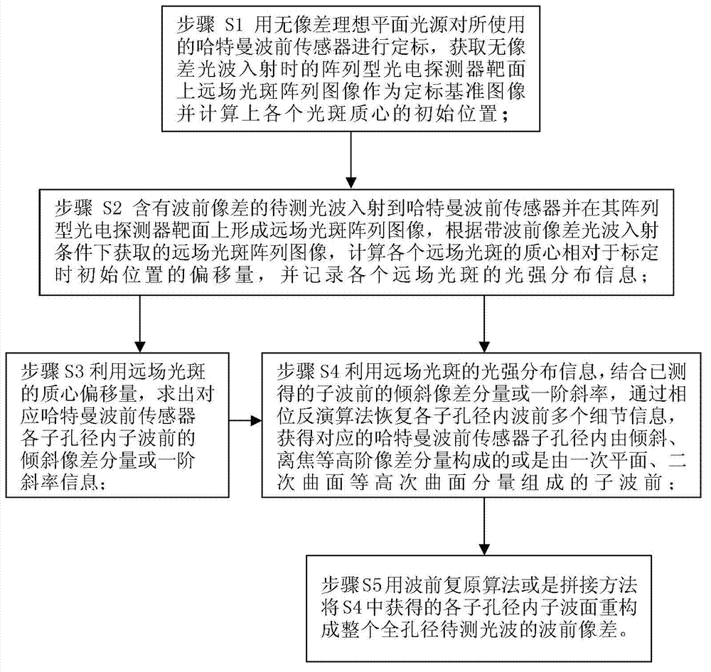
[0017] figure 1 The specific steps of the wavefront measurement method based on the Hartmann wavefront sensor include:

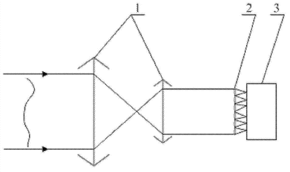
[0018] Step S1: Calibrate the Hartmann wavefront sensor with an aberration-free ideal planar light source to obtain an array photodetector 3( figure 2 Show) the far-field spot array image on the target surface as the calibration reference image, and calculate the initial position of each spot centroid on the calibration reference image;

[0019] Step S2: The light wave to be measured with wavefront aberration is incident on the Hartmann wavefront sensor and forms a far-field spot array image on the target surface of its array photodetector 3, which is obtained under the incident condition of light wav...


PUM


Abstract

The invention relates to a wavefront measuring method based on a Hartmann wavefront sensor. According to the method, light spot array images detected by an array type photoelectric detector in the Hartmann wavefront sensor are used for obtaining the intensity distribution information of each light spot and the mass center position offset relative to the calibration time, the inclination aberration information of a sub wavefront in the corresponding sub aperture can be obtained according to the mass center offset, the high order aberration information of defocusing, astigmatism and the like ofthe sub wavefront in the corresponding sub aperture can be obtained by a phase inversion algorithm according to the intensity distribution information of the light spot, the inclination aberration information and the high order aberration information are combined to form sub wavefronts, and finally, all sub wavefronts are reconstructed by a wavefront reconstruction method or a wave surface split joint method for forming the whole aperture wavefront information. The method has the advantages that the light spot dispersion distribution information which originally puzzles the light spot mass center calculation is utilized, more information quantity of the sub wavefronts in the sub aperture is obtained, the wavefront detection precision of the Hartmann wavefront sensor is favorably improved,or the requirement on the aperture number is favorably reduced.

Description

technical field [0001] The invention belongs to the technical field of optical information measurement, and relates to a method for measuring the wavefront of an incident light beam, in particular to a novel wavefront measurement method based on a Hartmann wavefront sensor. Background technique [0002] In adaptive optics, optical detection, photoelectric detection and other applications, it is necessary to measure the wavefront of the beam. Especially in adaptive optics systems, wavefront detection is an important prerequisite for adaptive control, which requires fast measurement of wavefront information for real-time wavefront control and correction. At present, many measurement methods have been applied in practice, such as shear interference wavefront sensing technology, Hartmann wavefront sensing technology, curvature wavefront sensing technology and phase inversion method, etc. These methods have their own advantages and disadvantages, and are used in various applicat...

Claims


Application Information

Patent Timeline
IPC IPC(8): G01J9/00
Inventor 王帅许冰杨平董理治刘文劲雷翔晏虎
Owner INST OF OPTICS & ELECTRONICS - CHINESE ACAD OF SCI
Why Eureka
Eureka Blog
Learn More