Screw retaining ring

A screw buckle and self-tapping screw technology, applied in the direction of connecting components, gaskets, mechanical equipment, etc., can solve the problems of difficult installation of metal plates, easy to fall off, etc., and achieve the effect of improving the pull-out force

Inactive Publication Date: 2012-10-17
NIFCO INC
View PDF10 Cites 4 Cited by
  • Summary
  • Abstract
  • Description
  • Claims
  • Application Information

AI Technical Summary

Problems solved by technology

[0014] Since the aforementioned conventional swivel nut (Japanese Patent Application Laid-Open No. 09-72323) has claws on the upper...

Method used


Image

  • Screw retaining ring
  • Screw retaining ring
  • Screw retaining ring

Examples


Embodiment Construction

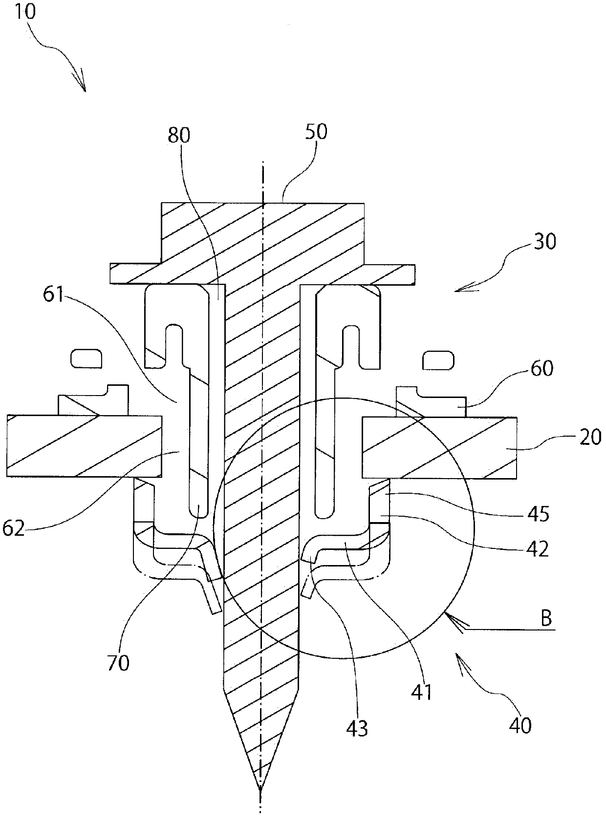
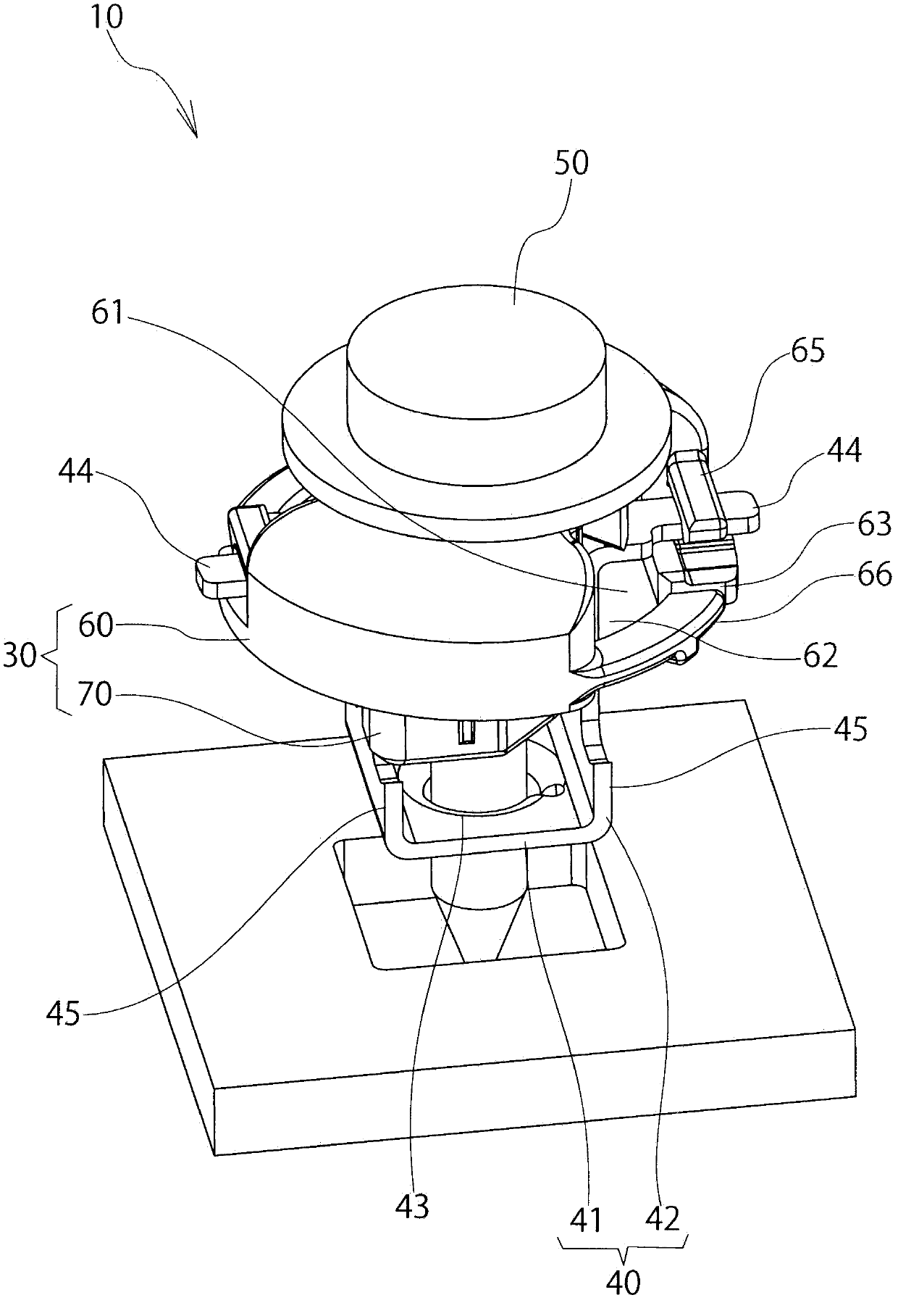
[0129] Among the figure, 10 is a screw clasp, such as figure 2 As shown, it is inserted into the mounting hole 21 of the component to be mounted 20 and mounted.

[0130] The mounted member 20 is a metal panel of an automobile or the like, has electrical conductivity, and has at least one surface thereof painted. like figure 2 As shown, the mounting hole 21 penetrates the front and back of the member 20 to be mounted, and is formed in a substantially square shape.

[0131] In addition, as the mounted member 20 , a metal panel such as an automobile is exemplified, but it is not limited to an automobile or a metal panel. In addition, although the mounting hole 21 is formed in a square shape, it is not limited thereto, and may be formed in other polygonal shapes, circular shapes, elliptical shapes, or the like.

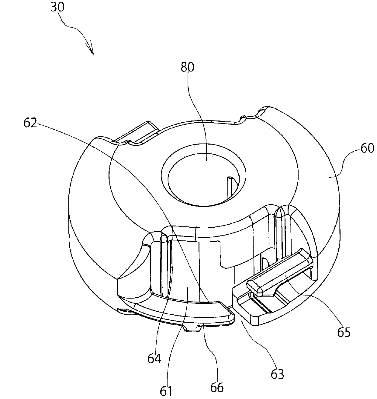
[0132] like Figure 1~6 As shown, the screw buckle 10 is generally composed of the following components.

[0133] In addition, the following (1)-(3) will be mentio...


PUM


Abstract

The invention provides a screw retaining ring. Via use of a metal plate, axial force can be set to a higher value, and reduction of the axial force caused by creep deformation and change of the axial force caused by plate thickness non-uniformity of a to-be-installed part such as a panel, etc. The screw retaining ring (10) comprises: a gasket (30) provided with a flange part (60) and a shaft part (70); and a metal plate (40) freely rotatably installed on the gasket (30), and provided with a base part with a screw thread hole (43) formed coaxial with an insertion hole (80) and a supporting foot (42) extending toward the flange part (60) and opposite to the back surface of the flange part (60). Via the shaft part (70) being inserted into an installing hole (21) of the to-be-installed part (20) such as the panel, a self-tapping screw (50) is screwed into the screw thread hole (43), the metal plate (40) is made to rotate and move axially, and therefore, the to-be-installed part (20) is clamped by the back surface of the flange part (60) and the supporting foot (42).

Description

technical field [0001] The present invention relates to a screw retainer. By using a metal plate, not only can the axial force be set high, but also the decrease of the axial force due to creep and the unevenness of the plate thickness of the mounted parts such as panels can be suppressed. The resulting change in axial force. Background technique [0002] In the past, there is known a first screw buckle in which the front end portion enters the inner side of the leg portion by fastening the screw so as to expand the leg portion (for example, refer to paragraph 0018 of Patent Document 1, Figure 4 and Figure 5 ). [0003] Conventionally, there is known a second screw buckle deformed so that the pillar protrudes by screwing (for example, refer to paragraph 0010 of Patent Document 2, Figure 10 and Figure 11 ). [0004] In the past, when a bolt is inserted, the rotating nut is rotated so that the rotating nut is raised by bolt tightening (for example, refer to paragraph 0...

Claims


Application Information

Patent Timeline
IPC IPC(8): F16B43/00F16B21/02H01R4/66
Inventor 斋藤考弘
Owner NIFCO INC
Why Eureka
Try Eureka