
Granulator with ring mould

A granulator and ring die technology, which is applied in the direction of mold extrusion granulation, presses, manufacturing tools, etc., can solve problems such as easy failure, high probability of support shaft breakage, and difficult maintenance

Inactive Publication Date: 2012-10-03
涂佳永
View PDF6 Cites 1 Cited by
  • Summary
  • Abstract
  • Description
  • Claims
  • Application Information

AI Technical Summary

Problems solved by technology

However, the supporting shaft of the pressure roller assembly, the main component of the existing feed pellet forming machine, is in the hollow shaft on the same side of the ring die, and is also a cantilever shaft. The support shaft of the pressure roller assembly has a high probability of breaking and is difficult to maintain.
The bearing of the pressing roller is in the pressing chamber, and its bearing is prone to failure when it operates in a high-temperature, high-pressure, and high-dust environment. It costs nearly 80 yuan to process bearings and butter per ton of wood pellets.
The applicant applied for a utility model patent with the application number 201120255389.6 on July 9, 2011. In this patent, the pressure roller bearing in the original pressing chamber was changed outside the pressing chamber, and the gap between the pressure roller and the ring die can also be Through the adjustment of the external eccentric sleeve, the failure rate of the equipment is reduced, and the service life of the bearing is effectively extended, but there are still certain limitations in practice.

Method used


Image

  • Granulator with ring mould
  • Granulator with ring mould
  • Granulator with ring mould

Examples


Embodiment Construction

[0015] The specific technical solution of the ring die granulator of the present invention will be further described below in conjunction with the accompanying drawings and preferred embodiments.

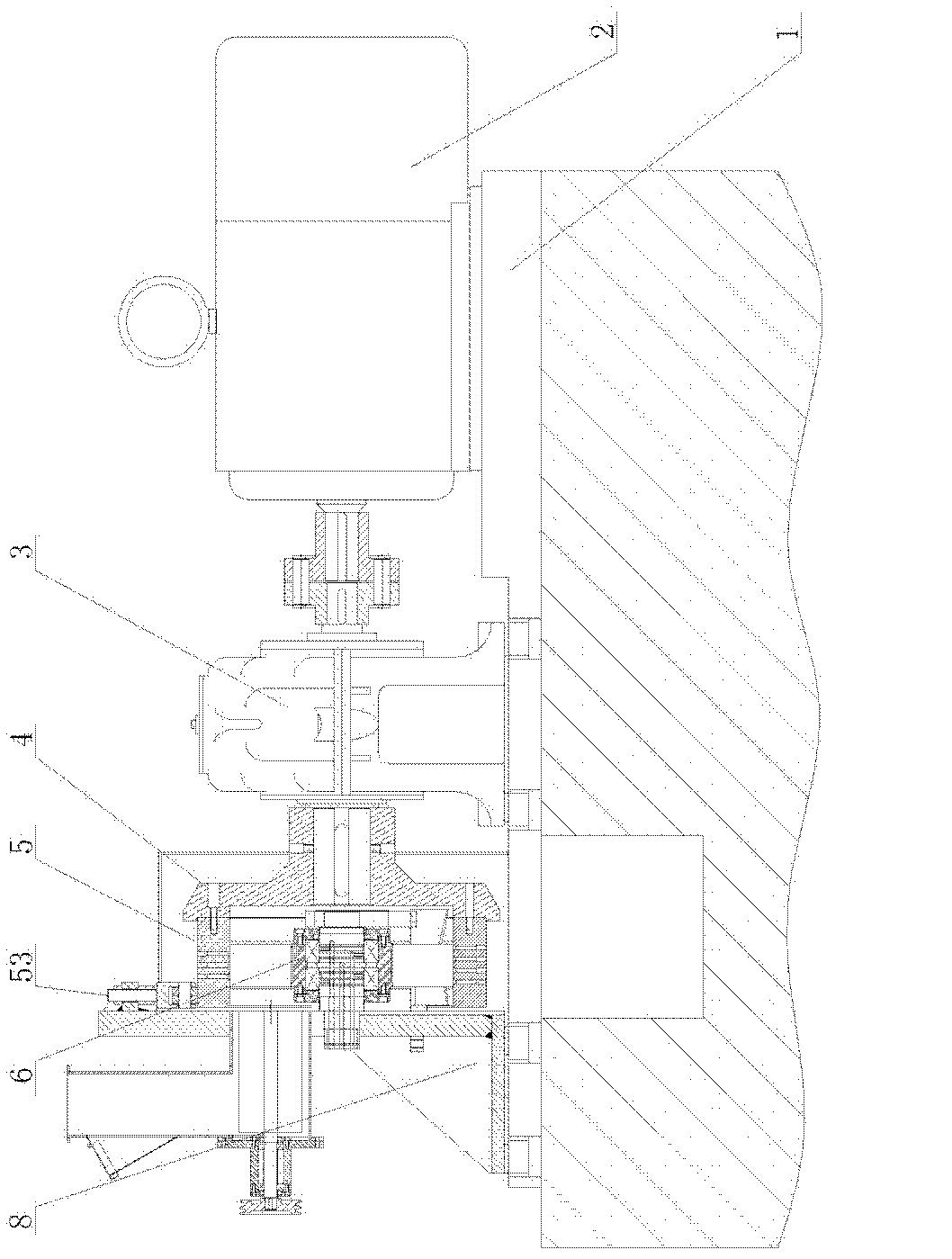
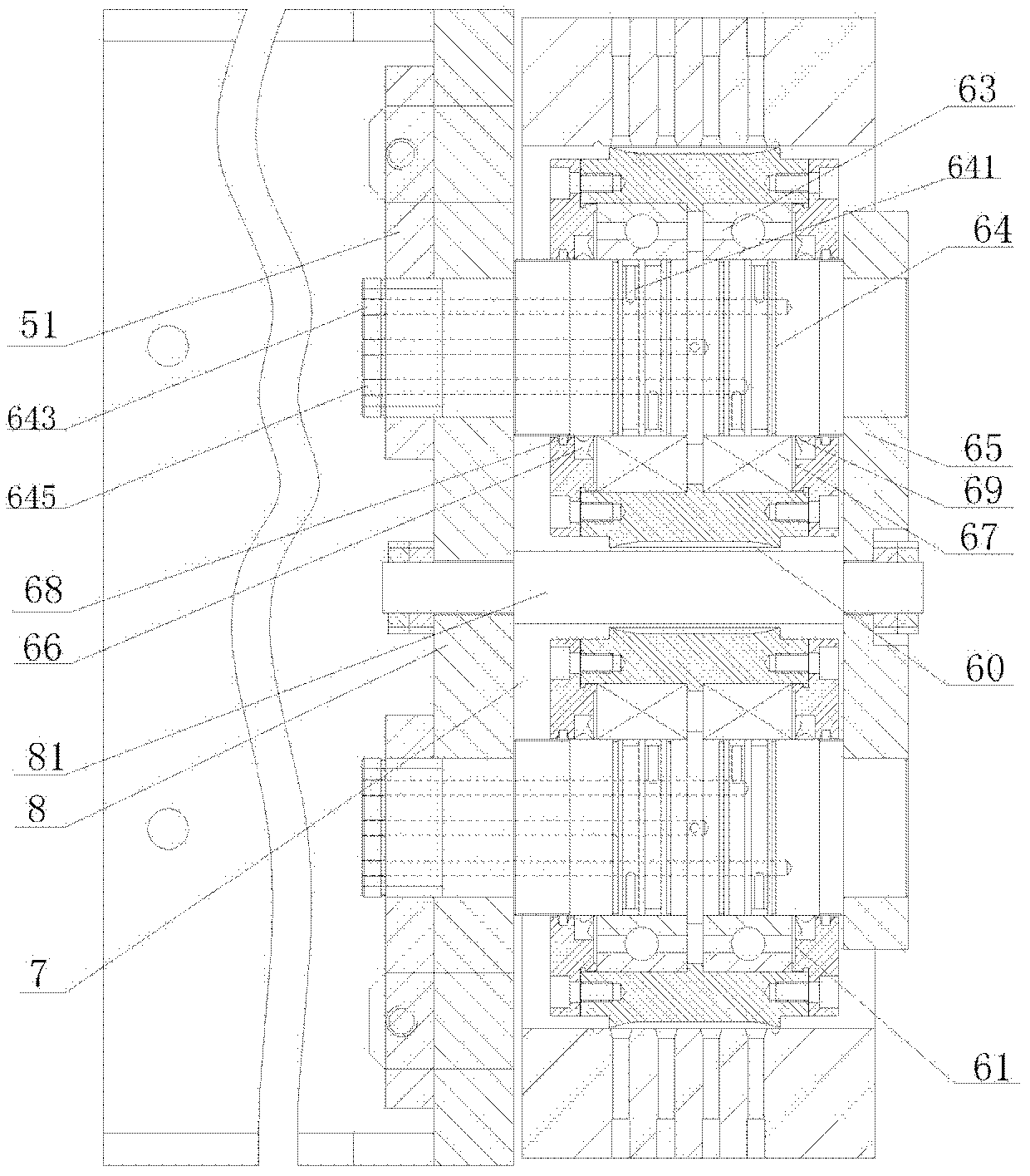
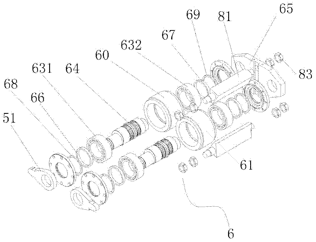
[0016] refer to Figure 1 to Figure 4 . A ring die granulator includes a machine base 1, a drive motor 2, a reducer 3, a ring die base 4 is installed on the output shaft of the reducer 3, the ring die base 4 is closely connected with a ring die 5, and the pressure roller assembly 6 is located on the In the ring die 5 , a pressing chamber 7 is formed with the ring die 5 , and the pressing roller assembly 6 includes a left pressing roller assembly 60 and a right pressing roller assembly 61 arranged symmetrically. The structure of the left pressing roller assembly 60 is the same as that of the right pressing roller assembly 61 , and the left pressing roller assembly 60 is taken as an example for illustration. The left pressure roller 62 of the left pressure roller assembly 60 is fixe...


PUM


Abstract

The invention discloses a granulator with a ring mould. The granulator with the ring mould comprises a base, a driving motor and a speed reducer. A ring mould base which is firmly connected with the ring mould is arranged on an output shaft of the speed reducer, a compression roller component is located in the ring mould and forms a compressing cavity with the ring mould, a compression roller of the compression roller component is fixed on a compression roller shaft via a compression roller bearing, the front portion of the compression roller shaft is arranged on a compression roller seat, the bottom end of the compression roller seat is arranged at the top end of the base, a connecting rod is arranged at the back end of the compression roller seat, the back end of the compression roller shaft is connected with a connecting plate which is connected to the back end of the connecting rod, and a ring groove is arranged on the circumferential surface of the compression roller shaft at the position of the compression roller bearing, and is communicated with axial cooling liquid inlets and axial cooling liquid outlets which are axially arranged on the compression roller shaft. Since the bearing is added to support the ring mould, negative factors brought by a ring mould cantilever are eliminated; since a liquid cooling device is added in the compression roller shaft, equipment failure rate is lowered, service lives of the bearing and the shaft are effectively prolonged, grease usage quantity of the bearing is reduced, and production efficiency is obviously improved.

Description

technical field [0001] The invention relates to the field of granulators, in particular to a ring die granulator in the application fields of biomass such as wood and stalks, feed and garbage. Background technique [0002] At present, there are relatively mature feed pellet molding machines in the domestic market, but there is no relatively mature wood pellet molding machine. Because the hardness of wood pellet raw materials is much greater than that of feed pellet raw materials, the pressure is high when processing wood pellets. ,High temperature. However, the supporting shaft of the pressure roller assembly, the main part of the existing feed pellet molding machine, is in the hollow shaft on the same side of the ring die, which is also a cantilever shaft. The fracture probability of the pressure roller assembly supporting shaft is high, and maintenance is difficult. The bearing of the press roller is in the press chamber, and its bearing is prone to failure when it operat...

Claims


Application Information

Patent Timeline
IPC IPC(8): B01J2/22
CPCB30B11/208B30B15/34
Inventor 涂佳永
Owner 涂佳永
Learn More