
Communication system and current amplifying device with input device whose input state is monitored

A communication system and current amplification technology, applied in the field of communication systems, can solve the problems of expensive sensors and unreliable identification of input current, and achieve the effect of reducing transition resistance

Active Publication Date: 2015-11-04
PHOENIX CONTACT GMBH & CO KG
View PDF5 Cites 0 Cited by
  • Summary
  • Abstract
  • Description
  • Claims
  • Application Information

AI Technical Summary

Problems solved by technology

Because the contacts of the sensor connected to the digital input device will eventually have a transition resistance, so that the input current can be reduced to such an extent that the input current cannot be reliably recognized by the input device
This defect can be reduced though with high quality contacts, such as gold plated contacts; however, sensors with such contacts are expensive

Method used


Image

  • Communication system and current amplifying device with input device whose input state is monitored
  • Communication system and current amplifying device with input device whose input state is monitored
  • Communication system and current amplifying device with input device whose input state is monitored

Examples


Embodiment Construction

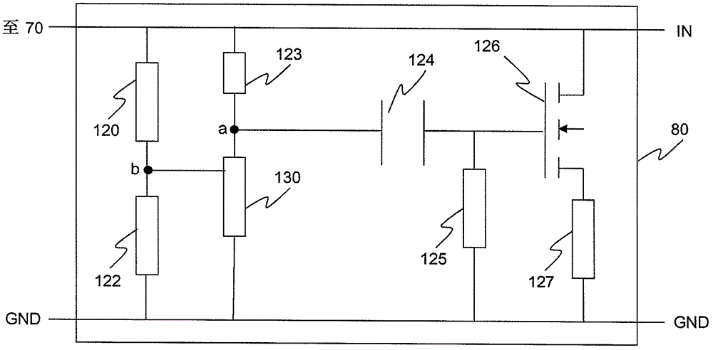
[0024] figure 1 An embodiment of a communication system 10 including an input device 20 is shown in FIG. The input means may be formed as a digital input device. It can be understood that the input device 20 can be an input and output device, a control device or a component of a field device, and the input device can have both a digital input and a digital output. The communication system 10 can work in offline operation, or can be an integral part of an automated machine.

[0025] The input device 20 can be provided with a supply voltage terminal U V , the supply voltage terminal is denoted by reference numeral 30 . At the supply voltage terminal 30 at a supply voltage U V Above, the supply voltage is provided by a DC power supply 40, for example. The DC power source 40 can be, for example, an external DC power source which is connected to the input terminals 52 and 54 of the input device 20 . The DC power supply 40 provides, for example, a supply voltage of 25 volts. ...


PUM


Abstract

The system (10) has input device (20) comprising input terminal (32) and ground terminal (34). An input circuit (70) is connected between input terminal and ground terminal for detecting an input signal. A sensor device (100) is connected to input terminal, and is optionally connected to ground terminal. A supply voltage source (40) is provided for supplying the sensor device with energy. A switched current increasing unit (80) is connected to input terminal and ground terminal, to supply high current to input circuit as a function of applied voltage for adjustable time period.

Description

technical field [0001] The present invention relates to a communication system with an input device whose input state is monitored; and a current amplifying device usable in the communication system. Background technique [0002] Even in automation technology, miniaturization based on circuit technology and device aspects is advancing more and more. As a result, measures must be taken to reduce losses in efficiency in devices and circuits. In digital input devices, the development of this aspect requires that the input current must be adjusted to smaller and smaller. In many application conditions, the input current is even lower than 5mA. Since the contacts of the sensor connected to the digital input device ultimately have transition resistances, the input current can be reduced to such an extent that the input current cannot be reliably detected by the input device. This defect can though be reduced by using high quality contacts, such as gold plated contacts; however ...

Claims


Application Information

Patent Timeline
Patent Type & Authority Patents(China)
IPC IPC(8): H03K19/0175H03F3/20
CPCH04Q9/00H04Q2209/88
Inventor 维克托·奥斯特
Owner PHOENIX CONTACT GMBH & CO KG
Learn More