
Semiconductor Lamp

A semiconductor and housing technology, applied in the field of semiconductor lamps, can solve the problems of glass bulbs, increase the time of hardening adhesives, and driver tension, and achieve the effects of reducing mechanical load, simplifying curling, and compact arrangement

Inactive Publication Date: 2017-09-12
LEDVANCE GMBH
View PDF8 Cites 0 Cited by
  • Summary
  • Abstract
  • Description
  • Claims
  • Application Information

AI Technical Summary

Problems solved by technology

The disadvantage here is that additional stations must be present in the production line
This must also significantly increase the time it takes to harden the adhesive
In addition, the problem of the sealing of the sleeve will also arise during the process of bonding the LED lamp
[0005] In yet another known variant, the board fitted with the LEDs is screwed to the housing, however this has the disadvantage of causing tension on the driver, especially its driver board
Screws also cost extra
Also, problems with glass bulbs can occur

Method used


Image

  • Semiconductor Lamp
  • Semiconductor Lamp
  • Semiconductor Lamp

Examples


Embodiment Construction

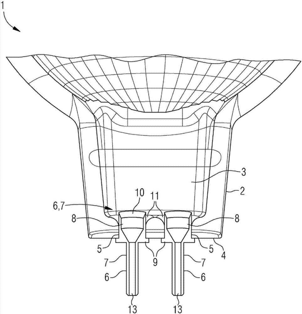
[0034] figure 1 A partial side sectional view of an LED-MR16 retrofit lamp 1 according to the invention is shown. The retrofit lamp 1 has a housing 2 in which a driver 3 is placed. Arranged on the rear end face 4 of the housing 2 are two bushings 5 ​​into which the respective contact pin 6 is inserted. Contact pins 6 are inserted into the sleeve 5 from the outside and protrude outward from the housing 2 . Thus, a pin-base is formed there.

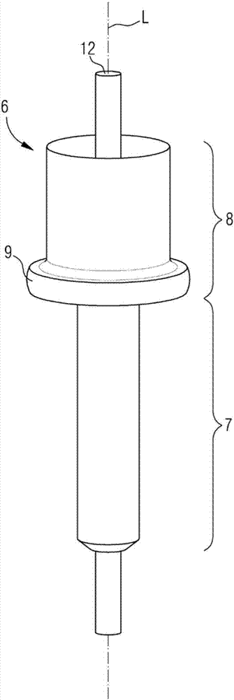
[0035] The contact pin 6 has a tubular or pin-like basic shape. This means that the outer-projecting contact section 7 has the shape of a hollow cylinder, which is compatible with conventional MR16 contact pins 102 . On the housing side, they each adjoin a widened section 8 , which is inserted into the sleeve 5 . The widened section 8 has an annular transverse projection or collar 9 in the transition to the contact section 7 . The collar 9 serves as a stop during the insertion of the respective contact pin 6 into the sleeve 5 and is on...


PUM


Abstract

A semiconductor lamp (1) comprises a housing (2) in which a driver (3) is accommodated and at least one contact pin (6) protruding from the housing (2) outwards, wherein the contact pin (6) is tubular and riveted to the housing (2) and the driver (3) is connected to the contact pin (6) via an electrically conductive connection element (12) which is inserted into a cavity (13) of the contact pin (6). A method serves for producing a semiconductor lamp (1), wherein at least one tubular contact pin (6) is inserted into a feedthrough (5) of a housing (2) from outside till the contact pin (6) abuts the housing (2), the contact pin (6) is next riveted with the housing (2) on the inside and a driver (3) is inserted into the housing (2), whereby an electrically conductive connection element (12) is inserted into the contact pin (6). The invention is particularly applicable to LED retrofit lamps for replacing bipin halogen lamps, in particular MR16 lamps.

Description

technical field [0001] The invention relates to a semiconductor lamp having a housing in which a driver is accommodated and at least one contact pin protruding from the housing. The invention finds particular application in LED retrofit lamps to replace pin-halogen lamps, especially MR16 lamps. Background technique [0002] LED lamps have hitherto been assembled complexly on a production line or manually from several components in several processing steps. A conventional MR16 retrofit lamp has a GU5.3-compatible base with two contact pins or "pins". Conventional LED-MR16-retrofit lamp 100 in Figure 4A An electronic driver 101 , partially shown in an oblique view, is supplied with electrical energy via contact pins 12 and converts it into drive signals for the LEDs (see figure). The driver 101 is fitted and soldered with contact pins 102 for this purpose. Such as Figure 4B Partially shown in an oblique view, the driver 101 is assembled into the housing 103 during the fi...

Claims


Application Information

Patent Timeline
IPC IPC(8): F21K9/23F21V23/06F21Y115/10
CPCF21V23/06F21K9/90H01J5/50H01R13/415F21Y2115/10H01J5/62F21K9/233F21K9/238F21K9/235H01R12/58H01R13/04H01R13/42H01R33/06
Inventor 托马斯·克拉夫塔迪特马尔·施密特
Owner LEDVANCE GMBH
Learn More