
Lighting apparatus of riding type vehicle

A technology for riding vehicles and lighting devices, which is applied to vehicle parts, bicycles, motorcycles, etc., can solve the problem of difficult to illuminate the main switch, difficult to illuminate the main switch, and difficult to see the function display of the main switch. and other issues to achieve the effect of improving visual recognition

Active Publication Date: 2012-09-26
HONDA MOTOR CO LTD
View PDF10 Cites 3 Cited by
  • Summary
  • Abstract
  • Description
  • Claims
  • Application Information

AI Technical Summary

Problems solved by technology

[0005] However, in the technology described in Patent Document 1, since the main switch and the lighting lamp are arranged on the same surface, the irradiation direction of the lighting lamp is parallel to the axis direction of the main switch and points in the same direction, so there is a problem that the irradiation light of the lighting lamp is difficult to According to the problem of the main switch
Especially when the light source of the lighting lamp adopts a power-saving light-emitting diode (LED), since the directivity of the irradiating light becomes high, if the main switch and the lighting lamp are buried on the same plane, the irradiating light can be effectively illuminated. Getting to the master switch becomes more difficult
In addition, the structure in which the irradiation light is irradiated onto the main switch from directly above the main switch, when the occupant operates the main switch, there is also the possibility that the irradiating light is blocked by the occupant's hand or the inserted portable key, and the total It is difficult to see the function display of the switch, etc.

Method used


Image

  • Lighting apparatus of riding type vehicle
  • Lighting apparatus of riding type vehicle
  • Lighting apparatus of riding type vehicle

Examples


Embodiment Construction

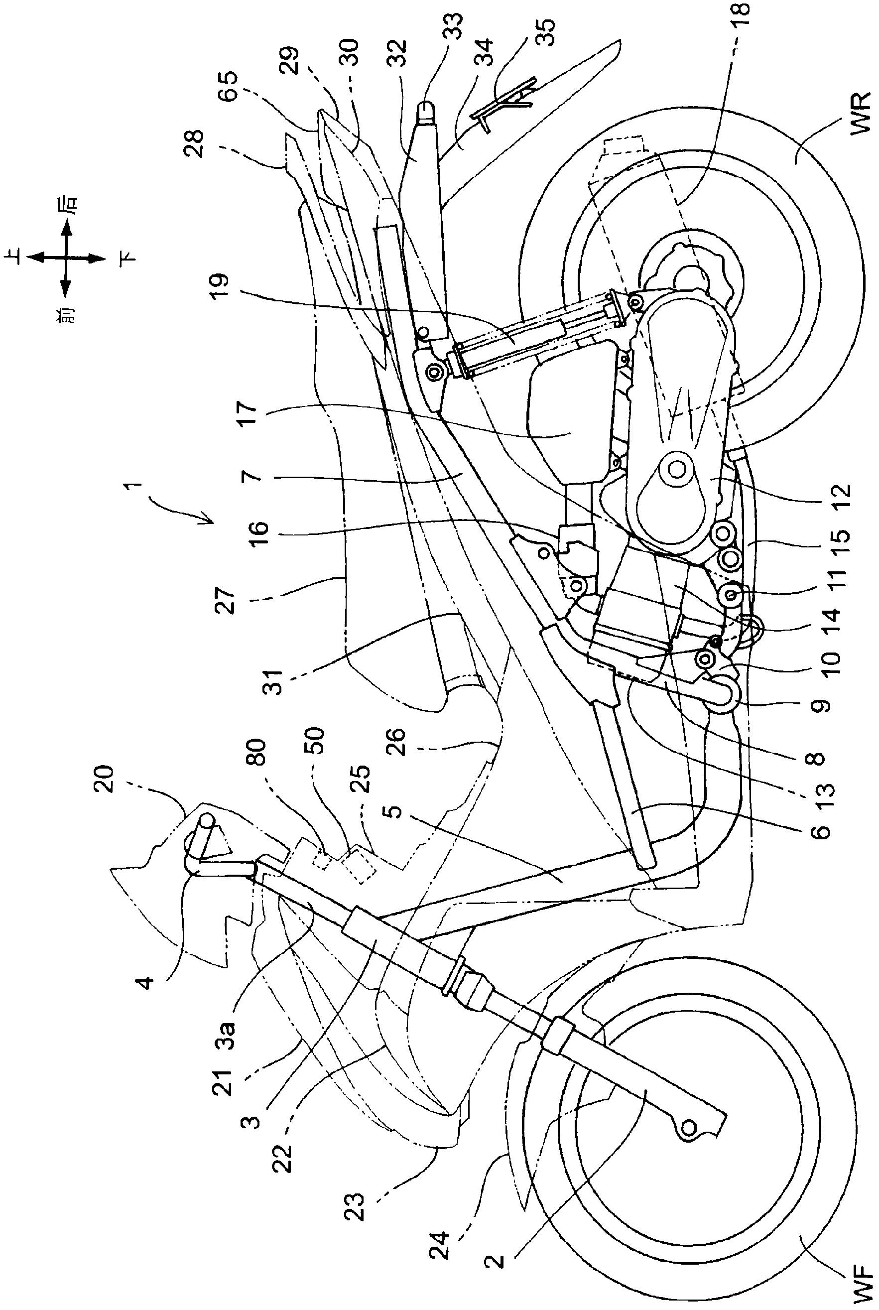
[0050] Hereinafter, preferred embodiments of the present invention will be described in detail with reference to the drawings. figure 1 It is a side view of a motorcycle 1 to which a lighting device for a saddle-riding vehicle according to an embodiment of the present invention is applied. The motorcycle 1 is a pedal-type saddle-riding vehicle, and has a swing assembly 12 integrating an engine and a drive system and a low-type footrest. A head pipe 3 is attached to a front end portion of the main frame 5, and the head pipe 3 pivotally supports a steering column 3a in a rotatable manner. A steering handle 4 is attached to the upper portion of the steering column 3a, and a pair of left and right front forks 2 are attached to the lower portion thereof, and the front forks 2 pivotally support the front wheel WF in a rotatable manner. The main frame 5 extending rearward and downward from the head pipe 3 is connected to a cross frame 9 pointing in the vehicle width direction after ...


PUM


Abstract

The invention provides a lighting apparatus of a riding type vehicle, wherein the light source type of the lighting apparatus is not restricted, the radiating light is not blocked by the key carried by the hand of a rider, and the key switch can be effectively lightened. A plane inclined portion (45) and a plane vertical portion (46) are formed on a leg guard plate (25) arranged opposite to a passenger, the inclined portion (45) is inclined foward wherein the portion above the vehicle is fronter than the portion below the vehicle, and the vertical portion (46) is vertically arranged from the inclined portion (45) to the portion above the vehicle. The portion lightened by the switch light (80) is positioned at the opening (45a) of the inclined portion (45) to be matched with a combined switch (50). The lighting surface of the switch light (80) is positioned at the opening (46a) of the vertical portion (46) to be matched with the switch light (80). When observed from the side of the vehicle body, the axis direction SJ of the lock core (56) of the combined switch (50) is crossed with the radiating direction PJ of the switch light (80) behind the vehicle body, and thereby the combined switch (50) is lightened from the front sideof the vehicle body.

Description

technical field [0001] The present invention relates to a lighting device for a saddle-type vehicle, and in particular to a lighting device for a saddle-type vehicle that illuminates a main switch for turning on and off the power supply of the vehicle by indirect lighting. Background technique [0002] Hitherto, lighting devices installed near the main switch (key switch) with indirect lighting to enable easy operation of the main switch of the saddle-riding vehicle even in dark environments such as nighttime are known. [0003] Patent Document 1 discloses a structure in which, in a pedal-type saddle-type two-wheeled vehicle having a handlebar cover for covering the handlebar, a substantially vertical surface provided on the rear side of the vehicle body of the handlebar cover is illuminated. On the main switch, the lighting made of incandescent lamps is installed on the same vertical plane and above the main switch. [0004] Patent Document 1: Japanese Utility Model Public...

Claims


Application Information

Patent Timeline
IPC IPC(8): B62J6/00B60R16/04B62K11/00
Inventor 安藤雅晴开田和宏松崎哲平
Owner HONDA MOTOR CO LTD
Learn More