
Leakage detecting device

A leak detection and cylinder block technology, which is applied in the direction of measuring the increase and decrease rate of the fluid, and using the liquid/vacuum degree to measure the liquid tightness, etc., which can solve the problems of complicated operation and long operation time

Inactive Publication Date: 2012-09-19
HUANGSHAN KENENG AUTO RADIATOR
View PDF7 Cites 19 Cited by
  • Summary
  • Abstract
  • Description
  • Claims
  • Application Information

AI Technical Summary

Problems solved by technology

Although this kind of leak detection device can block the outlet of the pipeline, it needs to install an additional inflation device when testing the air tightness. The workpiece can only be detected when the pressure of the larger chamber is higher than the pressure inside the workpiece, the operation is complicated and the whole operation time is long

Method used


Image

  • Leakage detecting device
  • Leakage detecting device
  • Leakage detecting device

Examples


Embodiment approach

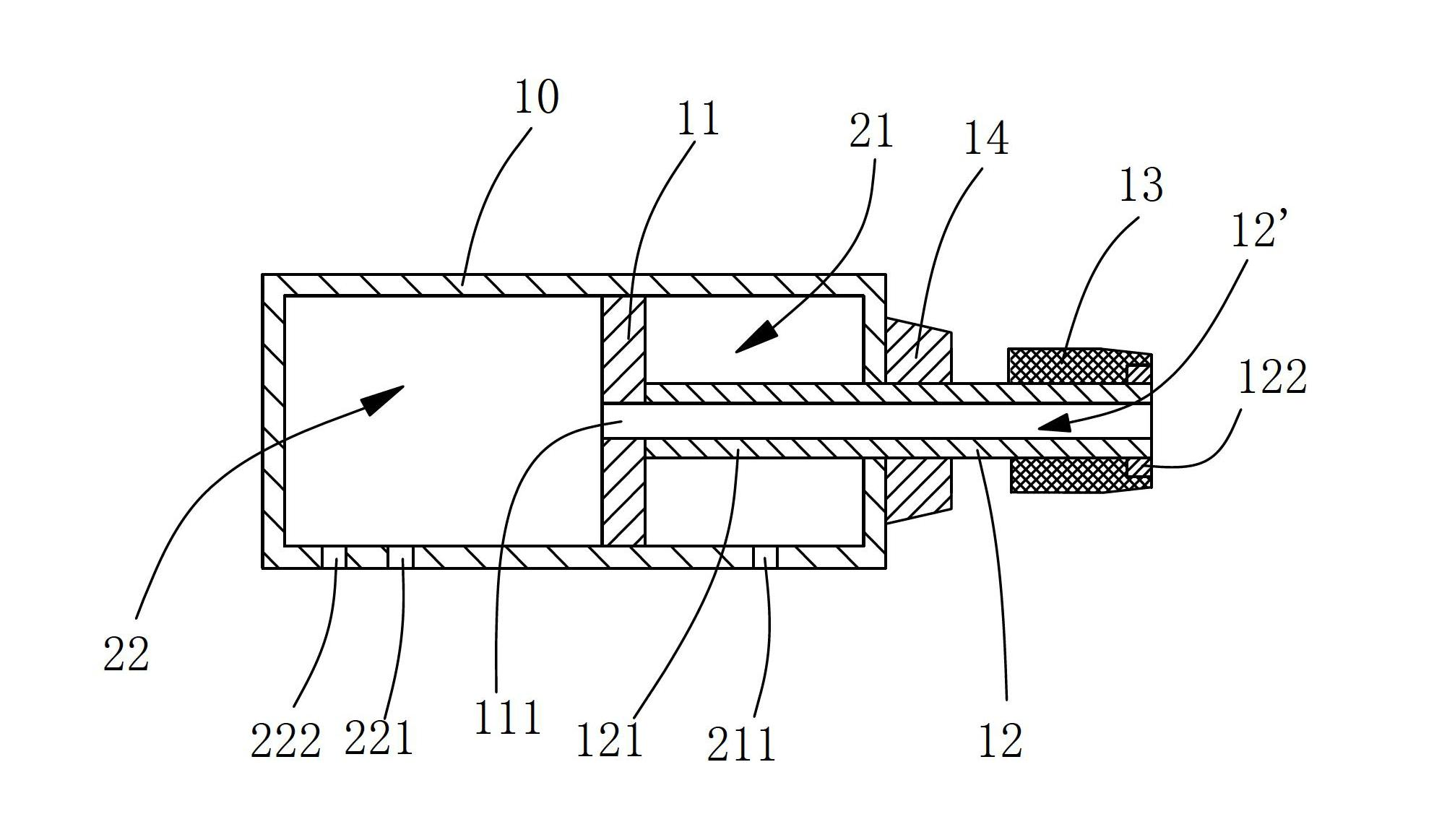
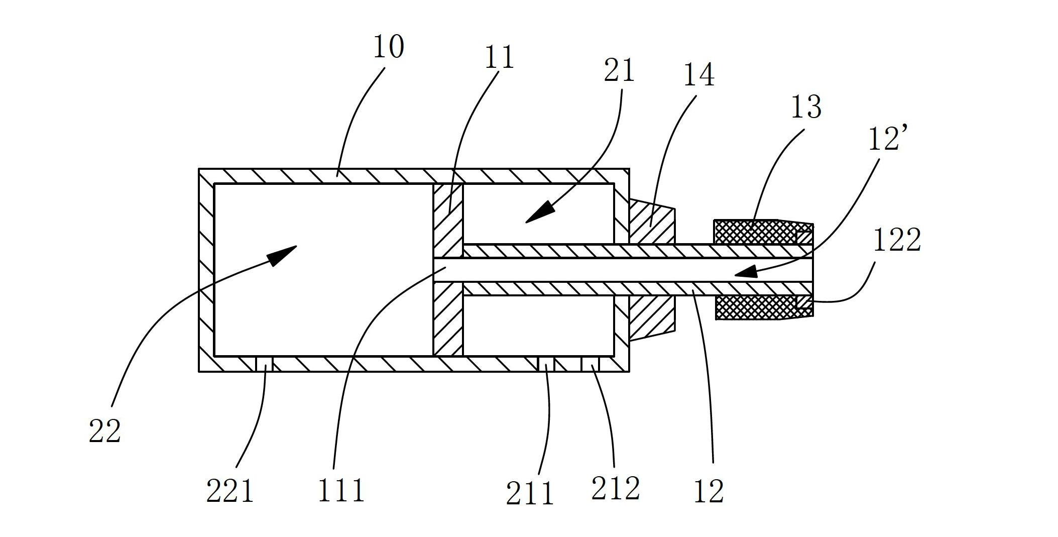
[0011] like figure 1 , 2 Shown is the first embodiment of the present invention, a third through hole 111 is opened at the plate surface where the piston 11 is connected to the piston rod 12, and the inflation channel 12' and the second chamber 22 pass through the third through hole 111. The through holes 111 are connected. The plug 13 is made of elastic material, and the diameter of the plug 13 is slightly smaller than the inner diameter of the connecting pipe 30 . In this embodiment, the plug 13 is put into the connecting pipe 30 in the initial state, and by rushing gas through the first through hole 221, the gas will fill the inside of the first chamber 21, thereby pushing the piston 11 and driving the plug 13 moves to the side close to the cylinder body 10, because a bracket 14 is arranged between the plug 13 and the cylinder body 10, and a through hole for the piston rod 12 is opened in the middle of the bracket 14, and the The outer end surface of the bracket 14 is fl...


PUM


Abstract

The invention discloses a leakage detecting device, comprising a cylinder body and a piston arranged in the cylinder body. A cavity inside the cylinder body is divided into a first cavity and a second cavity which are separated by the piston; a piston rod is arranged on the piston; a plug for blocking a pipeline opening of a workpiece is arranged on an end head extending outside the cylinder body of the piston rod; a first through hole and a second through hole, which are connected with a gas source, are respectively arranged in side walls of the first cavity and the second cavity; the piston rod is formed by a pipe body; and an air inflation channel formed in the pipe body is respectively communicated with a connection pipe and the first cavity / the second cavity. Gas is rapidly filled into the first cavity or the second cavity, which is separated from the air inflation channel, and the piston is pushed by the gas, so as to drive the plug to rapidly block the connection pipe. Meanwhile, the gas is filled into the other cavity, so that the gas is inflated into the workpiece through the air inflation channel, so as to realize the rapid leakage detection of the workpiece.

Description

technical field [0001] The invention relates to the field of radiator production equipment, in particular to a leak detection device for radiator leak detection. Background technique [0002] After the radiator is finished, it is necessary to test the welding quality of the welding points and the processing quality of the heat pipe. At present, the commonly used detection method is to inject gas into the inside of the radiator to make the inside of the radiator reach a certain pressure. By detecting the airtightness of the radiator at this time, the welding quality of each welding point on the radiator and the processing quality of the heat dissipation pipe are judged. Therefore, for large-scale continuous production, it is necessary to provide a leak detection device that can quickly seal the radiator and quickly inject gas into the radiator, so as to improve detection efficiency and reduce production costs. [0003] A Chinese patent document titled "A leak detection unit ...

Claims


Application Information

Patent Timeline
IPC IPC(8): G01M3/32
Inventor 方兴武
Owner HUANGSHAN KENENG AUTO RADIATOR
Learn More