Eureka AIR delivers breakthrough ideas for toughest innovation challenges, trusted by R&D personnel around the world.

Vacuum tank wall connector flange and installation method

An installation method and connector technology are applied in the field of new vacuum tank wall connector flange and installation, which can solve the problems of low flange reuse rate, high cost, type and quantity deviation of testing cables through the tank, etc. The effect of utilization rate, low maintenance cost and easy promotion

Active Publication Date: 2017-10-24
SHANGHAI INST OF SATELLITE EQUIP
View PDF2 Cites 0 Cited by
  • Summary
  • Abstract
  • Description
  • Claims
  • Application Information

AI Technical Summary

Problems solved by technology

[0002] Due to the different stand-alone and sub-systems of different satellites, there are large deviations in the type and quantity of the tank-through test cables during the vacuum thermal test of each satellite. At the same time, the size and installation method of different connectors are also very different, and special processing is often required according to requirements. Making vacuum tank wall connector flanges has a low reuse rate, which is not only expensive, but also faces great pressure for storage and storage

Method used


Image

  • Vacuum tank wall connector flange and installation method
  • Vacuum tank wall connector flange and installation method
  • Vacuum tank wall connector flange and installation method

Examples


Embodiment Construction

[0054] The present invention will be described in detail below in conjunction with specific embodiments. The following examples will help those skilled in the art to further understand the present invention, but do not limit the present invention in any form. It should be noted that those skilled in the art can make several modifications and improvements without departing from the concept of the present invention. These all belong to the protection scope of the present invention.

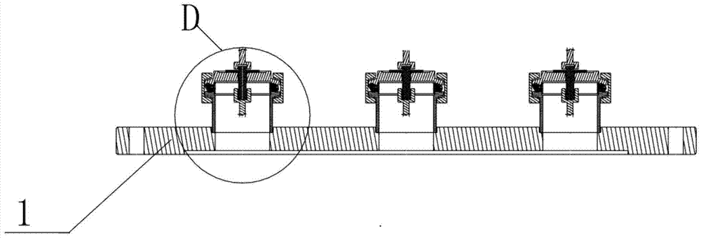
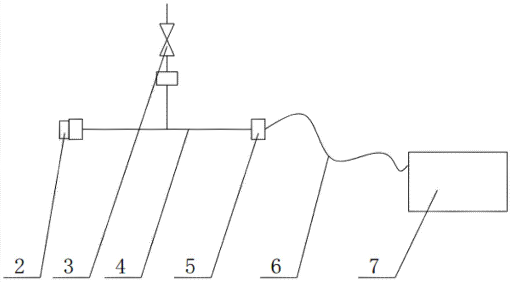
[0055] In this embodiment, the novel vacuum tank wall connector flange provided by the present invention includes a vacuum tank wall flange blind plate 1, a tank wall connector blind plate assembly 2, a quick release flange sealing assembly 5 and a quick release flange Connector 9; wherein, the vacuum tank wall flange blind plate 1 is provided with a plurality of quick release flange connectors 9; the tank wall connector blind plate assembly 2 is connected with the quick release flange sealing asse...


PUM


Abstract

The invention provides a novel vacuum tank wall connector flange, including a vacuum tank wall flange blind plate, a tank wall connector blind plate assembly, a quick-release flange sealing assembly and a quick-release flange connector; wherein the vacuum tank A plurality of quick-release flange connectors are arranged on the wall flange blind plate; the tank wall connector blind plate component is sealed and connected with the quick-release flange connector through the quick-release flange sealing component. The tank wall connector blind plate assembly includes the tank wall connector, the connector sealing ring and the quick-release flange blind plate; wherein, the quick-release flange blind plate is provided with a through hole; one end of the tank wall connector enters the quick-release flange through the through hole. The inner side of the flange connector; the connector sealing ring is set between the tank wall connector and the end surface of the quick release flange blind plate. In the present invention, the blind plate assembly of the tank wall connector is sealed and connected with the quick release flange connector through the quick release flange sealing assembly, which is suitable for connectors of various specifications and sizes, can improve the reuse rate of tank wall flanges, and reduce processing and production costs .

Description

technical field [0001] The invention relates to a flange, in particular to a novel vacuum tank wall connector flange and an installation method. Background technique [0002] Due to the different stand-alone and sub-systems of different satellites, there are large deviations in the type and quantity of the tank-through test cables during the vacuum thermal test of each satellite. At the same time, the size and installation method of different connectors are also very different, and special processing is often required according to requirements. Making vacuum tank wall connector flanges has a low reuse rate, which is not only expensive, but also faces great pressure for storage and storage. Therefore, there is an urgent need for a novel flange structure applicable to various connectors. Contents of the invention [0003] Aiming at the defects in the prior art, the object of the present invention is to provide a novel vacuum tank wall connector flange and installation metho...

Claims


Application Information

Patent Timeline
Patent Type & Authority Patents(China)
IPC IPC(8): B65D90/00B23P11/00
Inventor 张世一陈丽李宏宇冯晨曦谢飞峰沈超
Owner SHANGHAI INST OF SATELLITE EQUIP
Why Eureka
Eureka Blog
Learn More