
Clutch and separation device for running-in rack of engine

A separation device, engine technology, applied in the direction of engine testing, measuring device, machine/structural component testing, etc. performance and other issues, to achieve the effect of saving fault detection time, easy and labor-saving shifting operation, and ensuring performance and service life

Inactive Publication Date: 2012-09-12
力帆科技(集团)股份有限公司
View PDF6 Cites 2 Cited by
  • Summary
  • Abstract
  • Description
  • Claims
  • Application Information

AI Technical Summary

Problems solved by technology

At the moment of shifting, since the power transmitted from the engine to the transmission is not disconnected, there will be impacts between the internal gears of the transmission and between the shifting mechanisms, which may affect the shifting performance of the transmission, resulting in misjudgment (shifting card, not shifting) into the gear, etc.), and even the impact will cause damage to the internal components of the transmission, leaving hidden troubles and shortening the service life of the transmission
At the same time, the simulated shifting operation is difficult and laborious

Method used


Image

  • Clutch and separation device for running-in rack of engine
  • Clutch and separation device for running-in rack of engine

Examples


Embodiment Construction

[0014] Below in conjunction with accompanying drawing and embodiment the present invention will be further described:

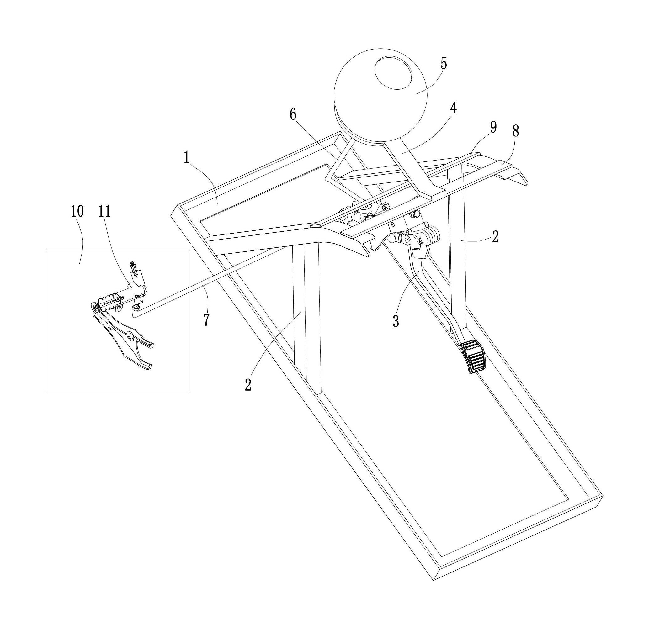
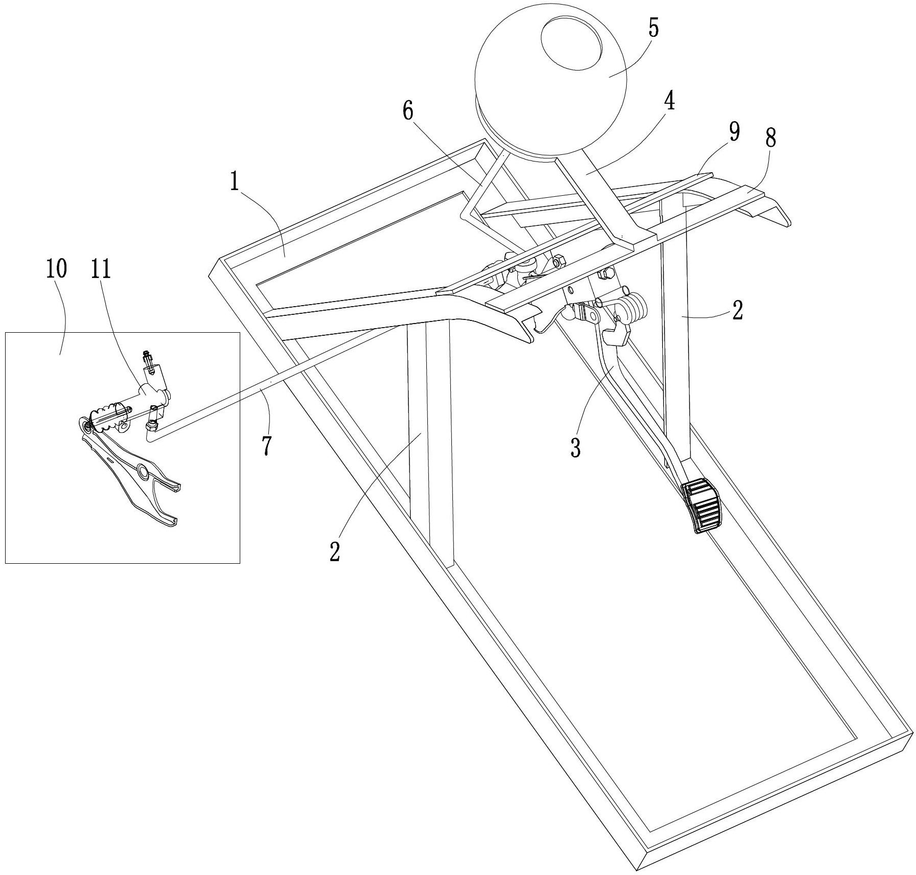
[0015] Such as figure 1 Shown, the present invention is made of components such as underframe 1, side support 2, clutch pedal assembly 3, upper support 4, oil storage tank 5, first oil pipe 6, second oil pipe 7, upper beam 8 and lower beam 9. Wherein, the bottom frame 1 is preferably a rectangular frame structure, and side brackets 2 are arranged on the front of the two long sides of the bottom frame 1, and the side brackets 2 on the left and right sides are symmetrically distributed. The side support 2 is preferably in the shape of a "person", the left side support 2 is on the same vertical plane as the long side on the left side of the underframe 1, and the right side support 2 is on the same vertical plane as the long side on the right side of the underframe 1. , and the front and rear ends of the bottom of the side support 2 are welded to the correspondi...


PUM


Abstract

The invention discloses a clutch and separation device for a running-in rack of an engine. Two bilateral side supports (2) are fixed on a chassis (1), a cross beam is connected between the upper parts of the two bilateral side supports (2) and provided with a clutch pedal assembly (3) and an upper support (4), an oil storage tank (5) is supported on the upper support (4) and connected with a main pump oil port of the clutch pedal assembly (3) by a first oil pipe (6), and the main pump oil port of the clutch pedal assembly (3) is connected with a second oil pipe (7). Through the principle for simulating clutch separation of the whole car, the abnormal sound fault position of the engine can be accurately found by a running-in person, the fault detection time of the engine can be saved, and the detection efficiency can be effectively improved; and the clutch separation device is further helpful for gear shifting simulation in running-in test of the engine, leading the gear shifting operation to be easy and effort-saving, and eliminates the misjudgment drawbacks including clamping in gear shifting and incapability of gear shifting in the background art.

Description

technical field [0001] The invention relates to an engine running-in stand, in particular to a clutch separation device of the engine running-in stand. Background technique [0002] At present, after the automobile engine is assembled off the assembly line, a running-in test is required to test the performance of the engine. During the running-in test, both the engine and the transmission are installed on the running-in stand, and the output shaft of the engine is connected with the input end of the transmission. Because the engine will emit noise when it is working, the gear transmission of the transmission will also emit noise. When there is a fault at the engine end, affected by the noise of the transmission, it is difficult for the running-in personnel to accurately judge the fault location, and further troubleshooting must be done, thus increasing the test process and running-in Labor intensity of personnel. [0003] In addition, when the engine is run-in on the bench...

Claims


Application Information

Patent Timeline
IPC IPC(8): G01M15/02
Inventor 龙伟李中友刘宇
Owner 力帆科技(集团)股份有限公司
Learn More