
Hydraulic control system for piston type energy accumulator

A hydraulic system and accumulator technology, applied in the field of hydraulic systems, can solve the problems of high installed power, serious energy consumption, and low adjustability of the pump-controlled hydraulic system, and achieve overall beautiful appearance, strong adjustability, and cost reduction Effect

Inactive Publication Date: 2012-02-29
TIANJIN TIANDUAN PRESS CO LTD
View PDF6 Cites 19 Cited by
  • Summary
  • Abstract
  • Description
  • Claims
  • Application Information

AI Technical Summary

Problems solved by technology

[0003] In the current domestic design and development of composite material presses, the pump-controlled hydraulic system is basically used (the high-pressure pump is used as the power source, various directional valves and pressure valves are used as control components, and finally the required flow and pressure of the actuator cylinder are used. The medium is provided to the oil cylinder within the period required by the molding process to make it the tonnage required by the molding process); however, the pump control hydraulic system has a large installed power, serious energy consumption, and low adjustability

Method used


Image

  • Hydraulic control system for piston type energy accumulator
  • Hydraulic control system for piston type energy accumulator

Examples


Embodiment Construction

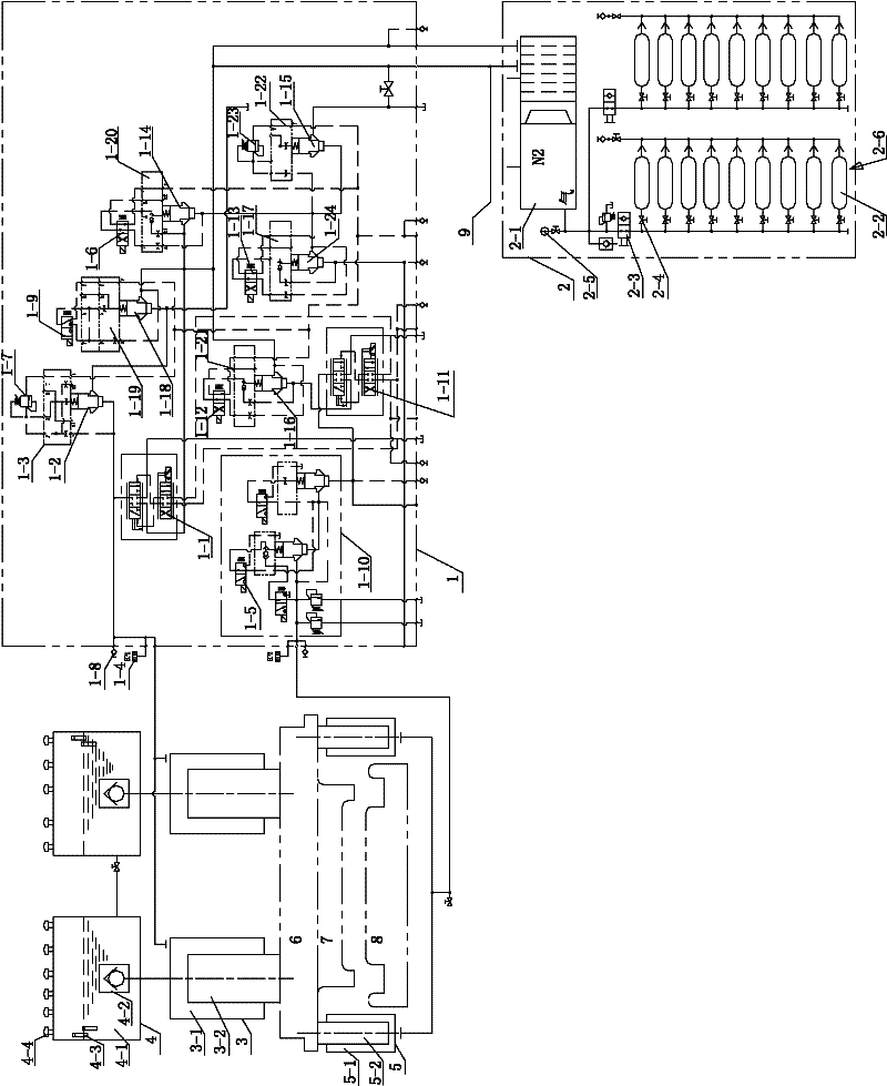
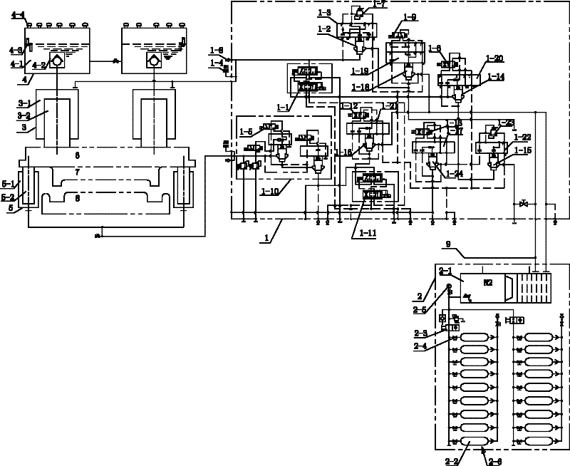
[0019] Specific embodiments are given below in conjunction with the accompanying drawings to further illustrate how the piston accumulator control hydraulic system of the present invention is realized.

[0020] Such as figure 1 As shown, the piston-type accumulator control hydraulic system of the present invention includes: a main cylinder 3 for driving the slider 6 to descend, and a liquid charging device 4 connected to the main cylinder 3 to charge the main cylinder 3 for driving the slider 6. The return cylinder 5 that the block 6 rises is also provided with a hydraulic system cartridge valve body 1 that communicates with the master cylinder 3 and the return cylinder 5 respectively for controlling the required flow and pressure of the master cylinder 3 and the return cylinder 5, and is provided with a valve body for storing Piston type accumulator station 2 for the hydraulic energy required by the system, the piston type accumulator station 2 is connected to the cartridge v...


PUM


Abstract

The invention discloses a hydraulic control system for a piston type energy accumulator, which comprises a main cylinder, a liquid filling device, a return cylinder, a hydraulic system spliced valve body and a piston type energy accumulator station, wherein the main cylinder is used for driving a sliding block to descend; the liquid filling device is connected with the main cylinder and is used for filling liquid into the main cylinder; the return cylinder is used for driving the sliding block to ascend; the hydraulic system spliced valve body is respectively communicated with the main cylinder and the return cylinder and is used for controlling the flow and the pressure required by the main cylinder and the return cylinder; the piston type energy accumulator station is used for storing hydraulic energy required by the system, is connected with the hydraulic system spliced valve body and comprises the piston type energy accumulator communicated with the hydraulic system spliced valve body through a pipeline; the piston type energy accumulator is connected with a gas cylinder group through a pipeline; and a one-way valve is arranged on a pipeline by which the gas cylinder group is communicated with the piston type energy accumulator. The hydraulic control system has the advantages that no hydraulic impact or obvious vibration is generated during high-and-low speed switching of a pressing machine, no shake, impact, noise or the like is generated during pressure relief of the main cylinder, the integral power of the pressing machine is greatly reduced, and the adjustability is stronger; hydraulic elements of the system, such as the motor, an oil pump, a valve bank and the like are greatly reduced; and the number of electrical control modules is decreased.

Description

technical field [0001] The invention relates to a hydraulic system, in particular to a hydraulic pressure system controlled by a piston type accumulator used in a composite material automobile part forming hydraulic press. Background technique [0002] As one of several important industries in the rapid development of my country's economy, the automobile industry has not only achieved rapid development in industrial scale in recent years, but also made great breakthroughs in industrial technology updates; however, with the continuous upgrading of industrial development , the automobile industry is facing three major issues of energy, pollution and safety, among which energy is the most prominent. When words such as "energy saving and emission reduction, global energy depletion, and new energy vehicles" are mentioned more and more frequently by the public, energy saving has become an important part of the development of the automobile industry. core issue. Energy saving is fir...

Claims


Application Information

Patent Timeline
Patent Type & Authority Applications(China)
IPC IPC(8): F15B1/02
CPCB30B15/163F15B1/08F15B2201/205F15B2201/31F15B2211/212F15B2211/775F15B2211/8606F15B2211/8616Y02E60/16
Inventor 王世明
Owner TIANJIN TIANDUAN PRESS CO LTD
Learn More