
Audio amplification circuit

An audio amplifying circuit and amplifier technology, applied in power amplifiers, improving amplifiers to reduce noise effects, etc., can solve the problems of unknown high-voltage PVDD setup time, startup noise, etc., and achieve the effects of eliminating startup noise, eliminating noise, and reducing costs.

Active Publication Date: 2012-08-15
SHANGHAI AWINIC TECH CO LTD
View PDF4 Cites 15 Cited by
  • Summary
  • Abstract
  • Description
  • Claims
  • Application Information

AI Technical Summary

Problems solved by technology

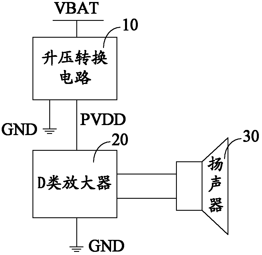
[0012] This is because the class D amplifier 20 is powered by high-voltage PVDD, and the class D amplifier 20 must be started after the high-voltage PVDD is stable, otherwise it will cause problems such as startup noise, but when using different control circuits, the system does not know the high-voltage PVDD Therefore, it may cause the high-voltage PVDD to be established, and the class D amplifier 20 has already started, thereby causing the problem of startup noise
[0013] Similarly, when using other types of audio power amplifiers (such as Class A amplifiers, Class B amplifiers, etc.), the problem of starting noise will also occur due to the independent existence of the control circuit.

Method used


Image

  • Audio amplification circuit
  • Audio amplification circuit
  • Audio amplification circuit

Examples


Embodiment Construction

[0050] As mentioned in the background art, in the prior art, in order to increase the power output of the audio amplifier circuit, it can usually be achieved by increasing the power supply voltage through a boost conversion circuit. In one implementation manner, the boost conversion circuit and the class D amplifier are respectively located on two chips, so that the cost thereof is relatively high, and the space occupied by the PCB board is large, which is not conducive to circuit integration.

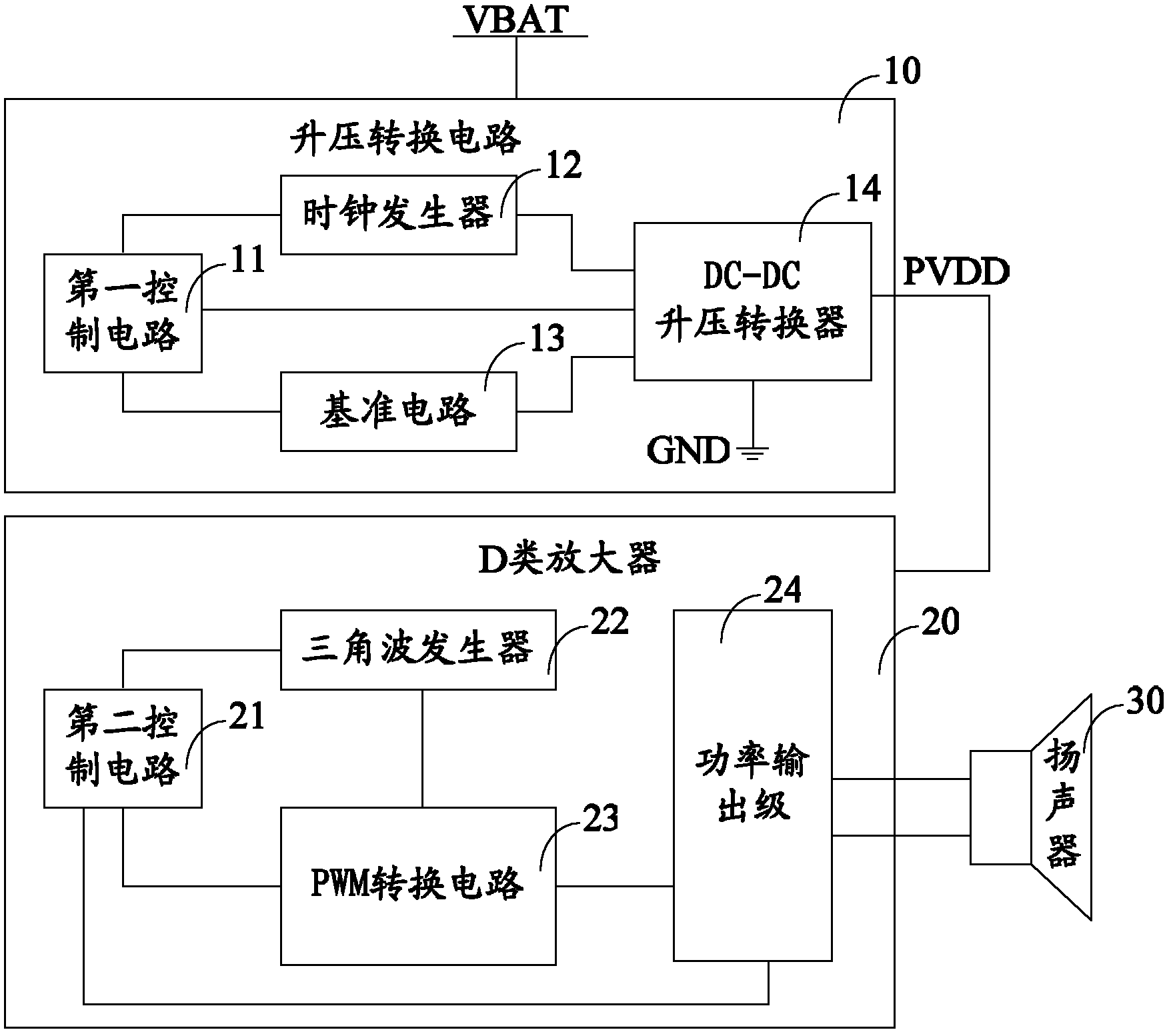
[0051] In another implementation, although the boost conversion circuit and the class D amplifier are integrated on the same chip, since the voltage rails of the boost conversion circuit and the class D amplifier are different, it is necessary to form their own control Circuits, clock generators, reference circuits and other peripheral circuits, and different control circuits may cause problems such as startup noise. Similarly, when other types of audio power amplifiers are used, the p...


PUM


Abstract

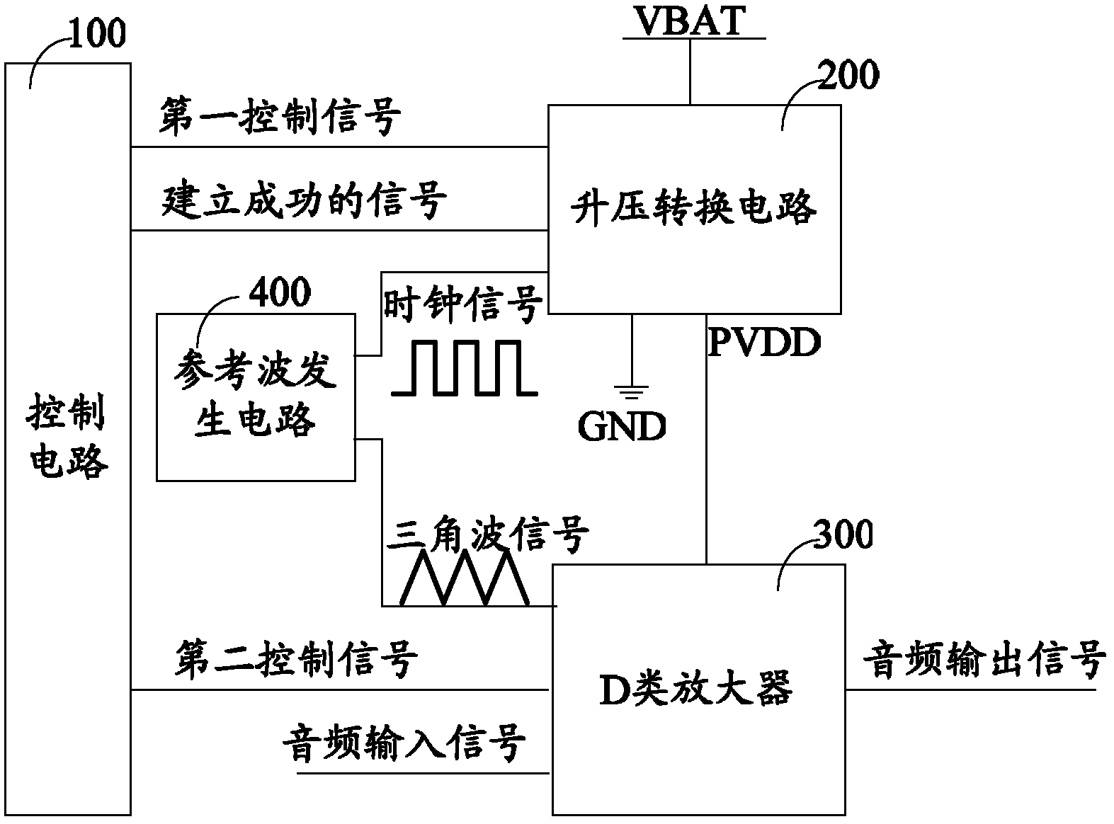
The invention discloses an audio amplification circuit comprising an audio power amplifier, a boosting conversion circuit and a control circuit, wherein the control circuit is used for generating a first control signal and a second control signal; the boosting conversion circuit is connected with the control circuit and the audio power amplifier and is used for converting power voltage to high voltage under the control of the first control signal, and the high voltage is used for supplying power to the audio power amplifier; the audio power amplifier is connected with the control circuit and is used for amplifying an audio input signal under the control of the second control signal and outputting an audio output signal; the boosting conversion circuit is used for sending a signal of successful establishment to the control circuit after the high voltage is established; and the control circuit sends the second control signal to the audio power amplifier after receiving the signal of successful establishment. The audio amplification circuit effectively eliminates starting noises caused by an independent control circuit.

Description

technical field [0001] The invention relates to the technical field of electronic circuits, in particular to an audio amplifier circuit. Background technique [0002] Nowadays, lithium batteries are usually used for power supply in portable systems. Due to the limitation of lithium battery voltage (usually up to 4.2V), the audio amplifier circuit power rail in the system is only up to 4.2V. If the differential output method is used, the output Peak V P The highest can reach about 4V, if there is no obvious truncated distortion, if the system load R L When it is 8Ω, the output power of the audio amplifier circuit In order to obtain better sound quality and greater volume, it is necessary to increase the power supply rail of the audio amplifier circuit. [0003] The traditional method usually uses a charge pump or an inductive DC-DC (direct-direct current) boost converter to increase the voltage of the lithium battery, supply the power after the voltage boost to the audio ...

Claims


Application Information

Patent Timeline
IPC IPC(8): H03F1/26H03F3/20
Inventor 张振浩杜黎明郭辉李俊杰管少钧万幸
Owner SHANGHAI AWINIC TECH CO LTD
Learn More