Control system for internal flow field of mesh-belt kiln

A control system, mesh belt kiln technology, applied in the flow field control system in the mesh belt kiln kiln, and in the field of calcining mesh belt kiln, it can solve the problems of catalyst cracking, difficult to ensure process requirements, product quality, process temperature error, etc., to achieve Good heat and moisture exchange, avoid catalyst cracking, stabilize temperature difference and humidity difference

Active Publication Date: 2012-08-15
JIANGSU FENGYE TECH ENVIRONMENTAL PROTECTION GRP CO LTD
View PDF6 Cites 1 Cited by
  • Summary
  • Abstract
  • Description
  • Claims
  • Application Information

AI Technical Summary

Problems solved by technology

During the cooling process, the catalyst will shrink in the length and width directions due to the loss of moisture. At this time, if the temperature field and humidity field in the kiln are too uneven, the moisture loss on the same catalyst will be different. Inconsistent shrinkage of the same catalyst in the transverse and longitudinal directions, leading to catalyst cracking
The current mesh belt kiln mostly adopts the natural cooling method, which makes the temperature in the firing section generally high, and the temperature in the cooling section is difficult to control. The actual temperature in the kiln has a large error from the set process temperature, and it is difficult to guarantee the process requirements and product quality.

Method used


Image

  • Control system for internal flow field of mesh-belt kiln
  • Control system for internal flow field of mesh-belt kiln
  • Control system for internal flow field of mesh-belt kiln

Examples


Embodiment Construction

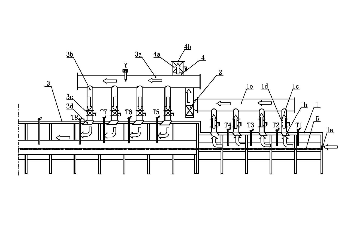
[0019] Such as figure 1 As shown, the flow field control system in the mesh belt kiln kiln of the present invention includes the high box 3 of the cooling section of the mesh belt kiln and the low box 1 of the cooling section of the mesh belt kiln, and the mesh belt 5 is located in the middle of the height direction of the high box 3 of the cooling section of the mesh belt kiln The lower box 1 of the cooling section of the mesh belt kiln extends horizontally, and the mesh belt 5 is tiled with a denitrification catalyst. The lower end of the tail air inlet 1a is flush with the mesh belt 5, and the top wall of the low box 1 of the mesh belt kiln cooling section is provided with a plurality of low box suction hoods 1b, and each low box suction hood 1b is respectively located in the mesh belt kiln cooling section The middle part of the width direction of the low box is evenly distributed along the length direction of the low box in the cooling section of the mesh belt kiln. Tilt ...


PUM


Abstract

The invention relates to a control system for an internal flow field of a mesh-belt kiln. A kiln tail air inlet is arranged at the tail of a low box in a cooling section of the mesh-belt kiln, a plurality of low box suction hoods are arranged on the top wall of the low box, an upper end opening of each low box suction hood is connected with a low box branch air duct, a low box air duct electric adjusting valve is arranged in each low box branch air duct, an upper end opening of each low box branch air duct is connected into a low box main air duct, the low box main air duct is connected with a suction opening of a cooling fan, an air outlet of the cooling fan is connected into a high box main air duct, the high box main air duct is positioned above the low box and extends along the height direction of a high box, a plurality of high box air outlet hoods are arranged on the top wall of the cooling fan, an upper end opening of each high box air outlet hood is connected with a high box branch air duct, a high box air duct electric adjusting valve is arranged in each high box branch air duct, and an upper end opening of each high box branch air duct is connected with the high box main air duct. By the aid of the control system for the internal flow field of the mesh-belt kiln, the temperature in the mesh-belt kiln can be more accurately controlled, and the manufacturing quality of denitration catalysts is improved.

Description

technical field [0001] The invention relates to a calcined mesh belt kiln for producing denitrification catalysts, in particular to a flow field control system in the mesh belt kiln, which belongs to the technical field of denitrification catalyst manufacturing facilities. Background technique [0002] The calcined mesh belt kiln for producing denitrification catalysts is equipped with a heating section, a first firing section, a second heating section, a second firing section and a cooling section along the direction of the mesh belt. Cool to set. During the cooling process, the catalyst will shrink in the length and width directions due to the loss of moisture. At this time, if the temperature field and humidity field in the kiln are too uneven, the moisture loss on the same catalyst will be different. The shrinkage of the same catalyst in the transverse and longitudinal directions is inconsistent, resulting in cracking of the catalyst. The current mesh belt kiln mostly ...

Claims


Application Information

Patent Timeline
Patent Type & Authority Applications(China)
IPC IPC(8): F27B9/12F27D9/00F27B9/40
Inventor 巫福明索平华攀龙仇荣胜李守信颜少云
Owner JIANGSU FENGYE TECH ENVIRONMENTAL PROTECTION GRP CO LTD
Why Eureka
Try Eureka