Automatic tool changing system of manipulator

A technology of automatic tool change and manipulator, applied in the direction of metal processing machinery parts, clamping, support, etc., can solve the problems of inapplicability of various machining centers, inapplicability of various spindles, mechanism damage, etc., and overcome the failure of loosening the tool Effect

Active Publication Date: 2012-08-08
淮南市启迪电子有限公司
View PDF10 Cites 4 Cited by
  • Summary
  • Abstract
  • Description
  • Claims
  • Application Information

AI Technical Summary

Problems solved by technology

[0003] The purpose of the present invention is to provide an automatic tool changing system for manipulators to overcome the hidden dangers of tool release failure and mechanism damage in the prior art that may be caused by a small amount of oil leakage or temperature changes, and that it cannot be applied to various spindles and multiple spindles. Insufficiency of this kind of machining center

Method used


Image

  • Automatic tool changing system of manipulator
  • Automatic tool changing system of manipulator
  • Automatic tool changing system of manipulator

Examples


Embodiment Construction

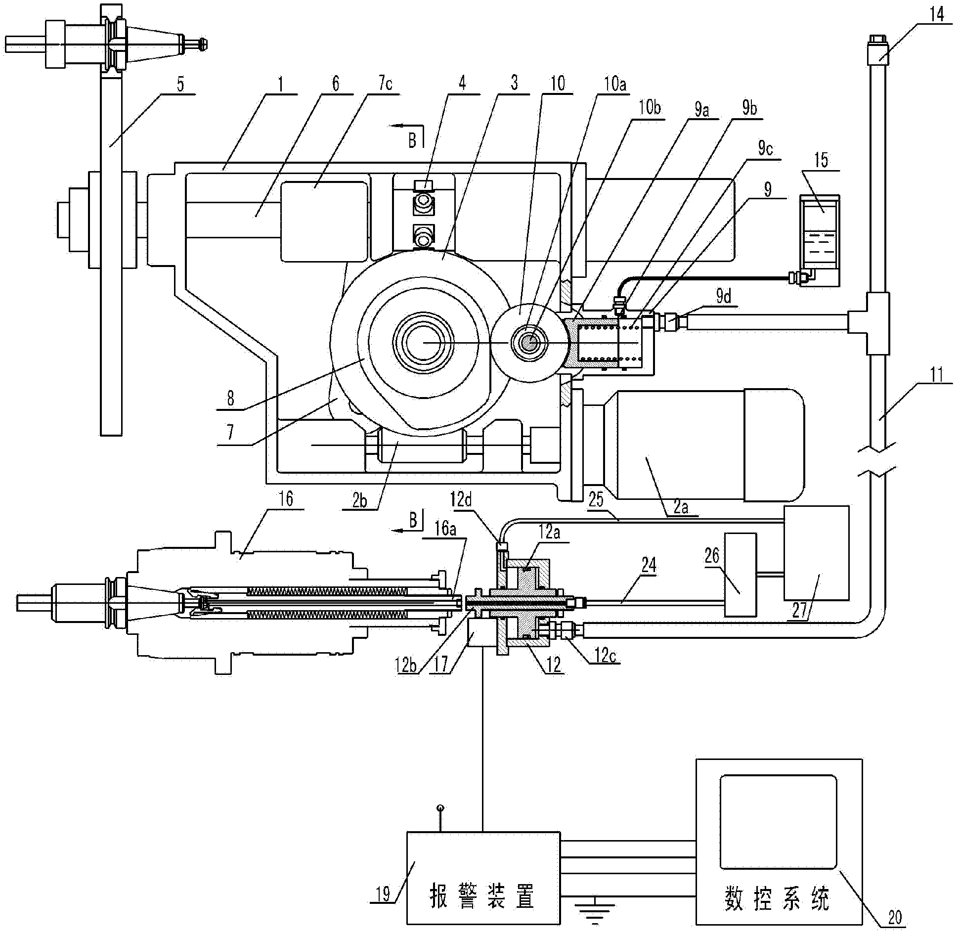
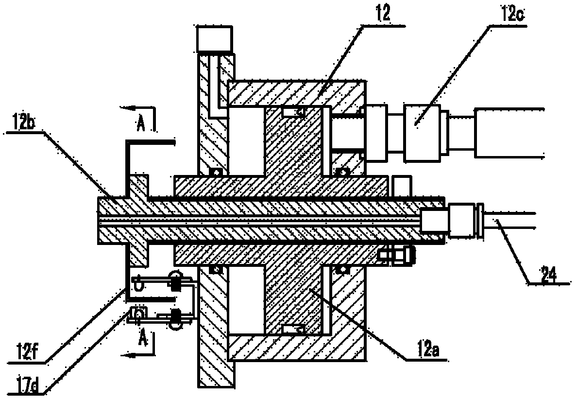
[0032] ginseng figure 1 , Figure 1a The manipulator automatic tool change system of the present invention consists of a housing 1, a brake motor 2a, a deceleration mechanism worm 2b, a deceleration mechanism worm gear 2c, a swing arm cam 3, a six-star wheel 4, a manipulator 5, a manipulator shaft 6, a knife insertion lever 7, Connecting rod 7b, bearing slider 7c, knife release cam 8, plunger oil pump 9, roller 10, high-pressure hose 11, knife release cylinder 12, knife release ejector rod 12b for adjusting the knife release stroke, with knife release rod 16a The main shaft 16, numerical control system 20, cam position switch 21 etc. constitute, the swing arm cam 3 is fixedly connected with the worm gear 2c of the reduction mechanism, and the annular cam groove on the outer circle of the swing arm cam 3 meshes with the six star wheel 4, and is made in or installed The inserting knife cam 13 on one side end face of the swing arm cam 3 meshes with the roller on the inserting kn...


PUM


Abstract

According to an automatic tool changing system of manipulator, a tool changing manipulator is driven to do swiveling motion and plugging-unplugging motion by a group of cam mechanism, and a tool loosening mechanism of a main shaft is driven by a system of oil pump, oil pipe, and oil cylinder to realize the coordination of the tool loosening-drawing action of the main shaft and the action of the manipulator. The whole process can be finished in only one start-stop action of the tool changing manipulator, and the tool changing speed is accelerated. But hidden trouble of damaging the tool changing mechanism exists in the system of oil pump, oil pipe, and oil cylinder, because the tool loosening-drawing action of the main shaft is not in place due to trace leakage of oil and change of temperature. According to the invention, the safety and the reliability of the whole tool changing process realized in one start-stop action of the tool changing manipulator are ensured by adding an oil supplementing hole on the oil pump, an oil supplementing cup, a tool loosening displacement detecting and alarming device, and a corresponding program of a numerical control system. The system of the invention is suitable for various kinds of main shafts by adopting normal tool loosening oil cylinder; the structure of the tool changing manipulator is simplified, and the volume is reduced by integrating a tool loosening cam with an arm swiveling cam, and the automatic tool changing system of the manipulator is further suitable for multiple machining centers such as vertical type and horizontal type.

Description

technical field [0001] The invention relates to an automatic tool changing system for a machining center, in particular to a tool changing system which utilizes a cam to realize coordinated control of manipulator and spindle loosening and broaching during the automatic tool changing process, and belongs to the technical field of metal cutting machine tools. Background technique [0002] Invention patent ZL200810011687.3, the name of the invention is: hydraulic cam linkage tool change mechanism of machining center, which proposes a manipulator automatic tool change mechanism different from the traditional technology. According to the traditional technology, the tool changer manipulator only undertakes the actions of turning the tool back and inserting the tool. During this process, it needs to cooperate with the spindle loosening and broaching mechanism. The two mechanisms need to be detected and coordinated by the CNC system. The manipulator needs to be started and stopped 3...

Claims


Application Information

Patent Timeline
Patent Type & Authority Applications(China)
IPC IPC(8): B23Q3/155
Inventor 邵文远
Owner 淮南市启迪电子有限公司
Why Eureka
Try Eureka