Apparatus for measuring charged particle beam energy utilizing optical method

A technology of charged particle beam and optical method, which is applied in the field of devices for measuring the energy of charged particle beam by optical method, can solve problems such as complex structure and limitation of radiation field strength, achieve high energy resolution, flexible and adjustable range, and solve high Intensity Pulsed Beam Particle Beam Energy Measurement Problem Effects

Active Publication Date: 2012-08-01
NORTHWEST INST OF NUCLEAR TECH
View PDF4 Cites 10 Cited by
  • Summary
  • Abstract
  • Description
  • Claims
  • Application Information

AI Technical Summary

Problems solved by technology

[0011] In order to solve the technical problems of the existing charged particle beam energy measurement devices, such as complex structure and limited by the intensity of the radiation field when used, the present invention provides a device that can be applied to both steady-state and pulsed radiation fields at the same time, with good energy resolution, wide range and simple A convenient and adjustable device for measuring the energy of charged particle beams by optical method

Method used


Image

  • Apparatus for measuring charged particle beam energy utilizing optical method
  • Apparatus for measuring charged particle beam energy utilizing optical method
  • Apparatus for measuring charged particle beam energy utilizing optical method

Examples


Embodiment

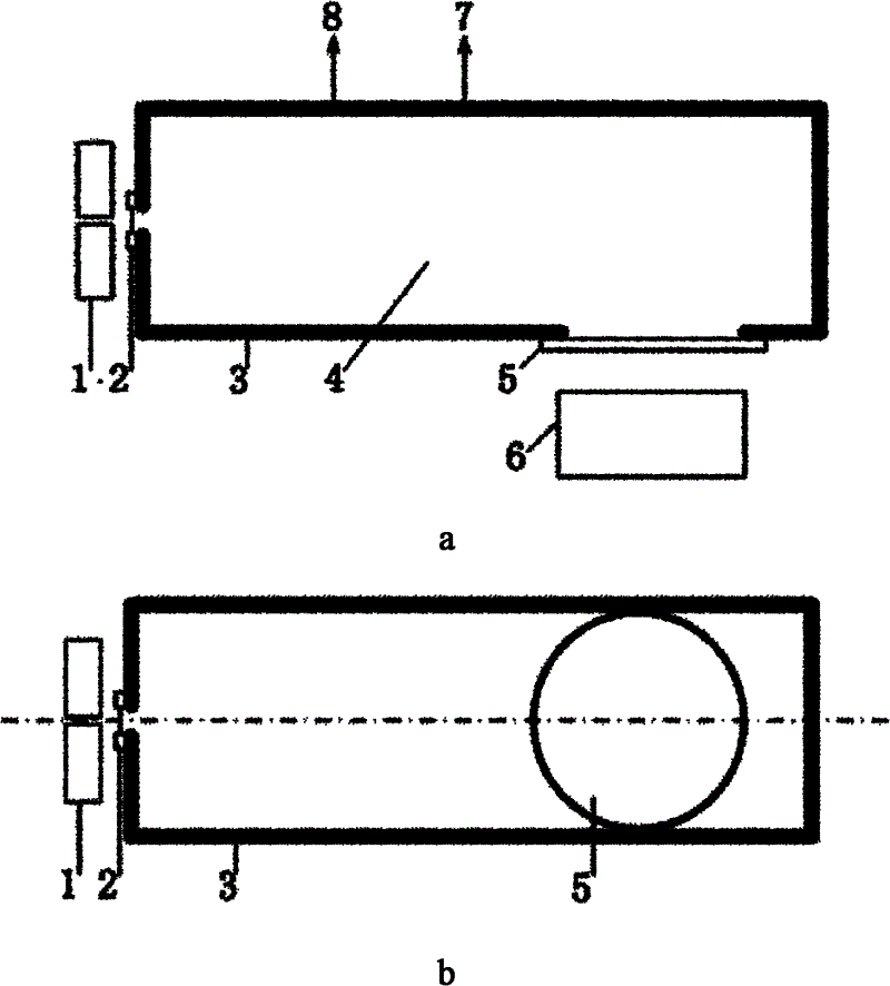
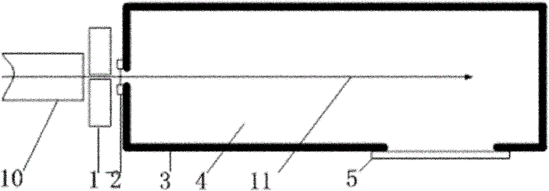
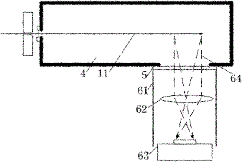
[0045] The size of the flashing light-emitting cavity 3 of the light-emitting component is 400mm×150mm×150mm. The flashing light-emitting cavity 3 is welded by A3 steel plate, and the front wall hole is The entrance window 2 is a 5μm titanium film with a diameter of Collimation shield 1 outer diameter The inner hole is The thickness is 20mm. The proton beam passes through the window of the accelerator beam pipe 10 , passes through the inner hole of the collimating shield 1 , and enters the gas scintillator 4 through the incident window 2 . The distance between the window of the beam duct 10 and the outside of the front surface of the scintillation light cavity 3 is 50mm. The size of the quartz glass window 5 is The thickness is 10mm, and the center of the quartz glass window is 260mm away from the front face of the flashing light-emitting cavity 3 . The material of the quartz glass window 5 is synthetic quartz (JGS1), and its transmittance is greater than 80% at 185n...


PUM


Abstract

The invention relates to an apparatus for measuring charged particle beam energy utilizing an optical method. The apparatus comprises a luminescent assembly and at least one imaging assembly. The luminescent assembly consists of a sealed scintillation luminous cavity filled with gaseous scintillators; and the imaging assembly includes a shading cylinder, a lens and an imaging device, wherein the shading cylinder is arranged on the scintillation luminous cavity. According to the invention, technical problems that an existing apparatus for measuring charged particle beam energy has a complex structure and is limited by radiation filed intensity when in use and the like are solved; meanwhile, the provided apparatus, which can be simultaneously applied to stable state and pulse radiation fields, has advantages of visual measurement, good energy resolution, wide measuring range as well as simple, convenient and adjustable properties and the like; moreover, the apparatus is suitable for energy measurement of various charged particle beams.

Description

technical field [0001] The invention relates to a device for optically measuring the energy of a charged particle beam. Background technique [0002] The energy spectrum is the main parameter index to characterize the characteristics of the radiation field, and it is an indispensable and important parameter in the research of nuclear physics and the application of nuclear technology. The energy of incident particles determines the process and nature of nuclear reactions, cross-section, reaction exit path, etc. Therefore, in nuclear physics research, it is necessary to know the change of the number of particles with energy, that is, the energy spectrum of particles. In ion therapy, in order to accurately calculate the dose of the irradiated area, it is also necessary to know the energy of the incident ions and the information of their deposition distribution. For example, in the case of proton (heavy ion) treatment of cancer, the radiation dose equivalent of protons changes ...

Claims


Application Information

Patent Timeline
Patent Type & Authority Applications(China)
IPC IPC(8): G01T1/29G01T1/36
Inventor 欧阳晓平刘金良张忠兵陈亮韩长才
Owner NORTHWEST INST OF NUCLEAR TECH
Why Eureka
Try Eureka