
Pulverized coal decoupling combustor with low nitrogen oxide discharge and pulverized coal decoupling combustion method with low nitrogen oxide discharge

A low-nitrogen oxide and burner technology, which is applied in combustion methods, burners for burning powder fuel, burners, etc., can solve the problem of difficulty in realizing large-scale decoupling combustion furnaces, achieve stable combustion and inhibit NOx generation. , increase the temperature, reduce the effect of turbulence and eddy current

Inactive Publication Date: 2012-08-01
INST OF PROCESS ENG CHINESE ACAD OF SCI +2
View PDF7 Cites 32 Cited by
  • Summary
  • Abstract
  • Description
  • Claims
  • Application Information

AI Technical Summary

Problems solved by technology

However, these patents above are only suitable for layered combustion technology, and are only suitable for small and medium-sized decoupled combustion furnaces below 20 tons / h, and it is difficult to realize large-scale decoupled combustion furnaces for pulverized coal combustion.

Method used


Image

  • Pulverized coal decoupling combustor with low nitrogen oxide discharge and pulverized coal decoupling combustion method with low nitrogen oxide discharge
  • Pulverized coal decoupling combustor with low nitrogen oxide discharge and pulverized coal decoupling combustion method with low nitrogen oxide discharge
  • Pulverized coal decoupling combustor with low nitrogen oxide discharge and pulverized coal decoupling combustion method with low nitrogen oxide discharge

Examples


Embodiment Construction

[0043] Further describe the present invention below in conjunction with accompanying drawing and embodiment

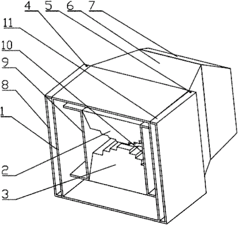
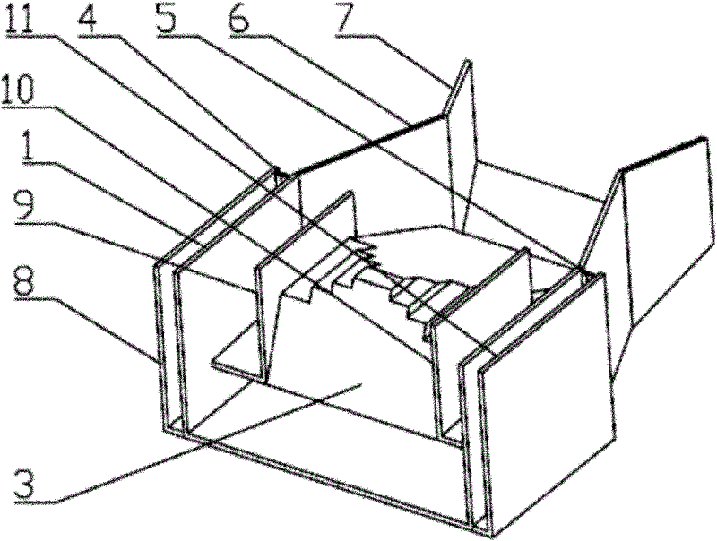
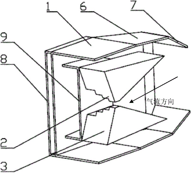
[0044] figure 1 It is a structural schematic diagram of the burner nozzle in the pulverized coal decoupling burner with low nitrogen oxide emissions of the present invention; figure 2 It is a structural schematic diagram of the burner nozzle opening the upper side plate of the burner nozzle; image 3 It is a schematic diagram of the structure of the burner nozzle opening the right side panel of the burner nozzle; Figure 4 Structural diagram for opening the burner nozzle on the upper side plate and the right side plate of the burner nozzle; Figure 5 for figure 1 main view of Figure 6 for figure 1 top view of Figure 7 for figure 1 left view of . As can be seen from the figure, the pulverized coal decoupling burner with low nitrogen oxide emissions of the present invention is composed of a burner body and a burner nozzle connected to the front port of the...


PUM


Abstract

The invention relates to a pulverized coal decoupling combustor with low nitrogen oxide discharge and a pulverized coal decoupling combustion method with low nitrogen oxide discharge. The method is implemented through the following two stages: a) stage 1, firstly separating mixed airflow of pulverized coal and air into a concentrated part and a dilute part by virtue of the pulverized coal decoupling combustor provided by the invention, igniting the concentrated pulverized coal airflow, then feeding the concentrated pulverized coal airflow into a hearth, and performing combined combustion on the concentrated pulverized coal airflow and the dilute pulverized coal airflow; and b) stage 2, mixing the mixed airflow with secondary air in the hearth, and fully combusting the pulverized coal semicoke generated in the stage 1 under conditions of rich oxygen and high temperature which is insufficient to generate thermal NOx, wherein in the stage 1, the pulverized coal is pyrolyzed, gasified and gas-fired under reducing atmosphere, volatile components are fully separated out, products of pyrolysis and gasification are utilized to convert fuel-type NOx into more stable N2. According to the invention, an integration design of pulverized coal condensation, stable combustion and low nitrogen oxide discharge can be realized, the equipment structure is compact, the pulverized coal condensation effect is good, the stable combustion capability is strong, and the potential of inhibiting NOx from generating is high.

Description

technical field [0001] The invention belongs to the field of pulverized coal combustion equipment, and in particular relates to a pyrolysis gasification pulverized coal decoupling burner and a pulverized coal decoupling combustion method with low nitrogen oxide emissions. Background technique [0002] In the practical application of pulverized coal combustion, as the combustion temperature and oxygen concentration of the pulverized coal-air mixture in the combustion stage increase, the content of fly ash combustibles (unburned carbon and CO) in the flue gas decreases, and the pulverized coal is easier to burn quickly , fully burn out; at the same time, the high temperature and oxygen enrichment will make the NO generated in the combustion process x On the other hand, the lower the combustion temperature and oxygen concentration of the pulverized coal-air mixture in the combustion stage, the better the suppression of nitrogen oxides NO x Generated, but coal dust is less like...

Claims


Application Information

Patent Timeline
IPC IPC(8): F23D1/00
CPCY02E20/34
Inventor 郝江平高士秋李静海蔡连国许光文
Owner INST OF PROCESS ENG CHINESE ACAD OF SCI
Learn More