Purified flue gas recycling device

A technology for recycling and cleaning flue gas, which is applied in the field of cleaning flue gas recycling and processing devices and cleaning flue gas recycling and processing devices, can solve the problems of large water consumption and waste of water resources, and achieve recycling, water saving, The effect of solving the recycling problem

Inactive Publication Date: 2012-08-01
田鹏程
View PDF5 Cites 10 Cited by
  • Summary
  • Abstract
  • Description
  • Claims
  • Application Information

AI Technical Summary

Problems solved by technology

[0002] At present, flue gas purification technologies such as wet desulfurization and denitrification are widely used. In the purification process, the common problem is that the water consumption is relatively large. The main manifestation is that after purification, a large amount of water is carried and discharged by the clean flue gas, resulting in huge water Waste of resources, especially in water shortage areas, the seriousness of this problem is more prominent, therefore, the problem of recycling and utilization of water in clean flue gas needs to be solved urgently

Method used


Image

  • Purified flue gas recycling device
  • Purified flue gas recycling device
  • Purified flue gas recycling device

Examples


Embodiment 1

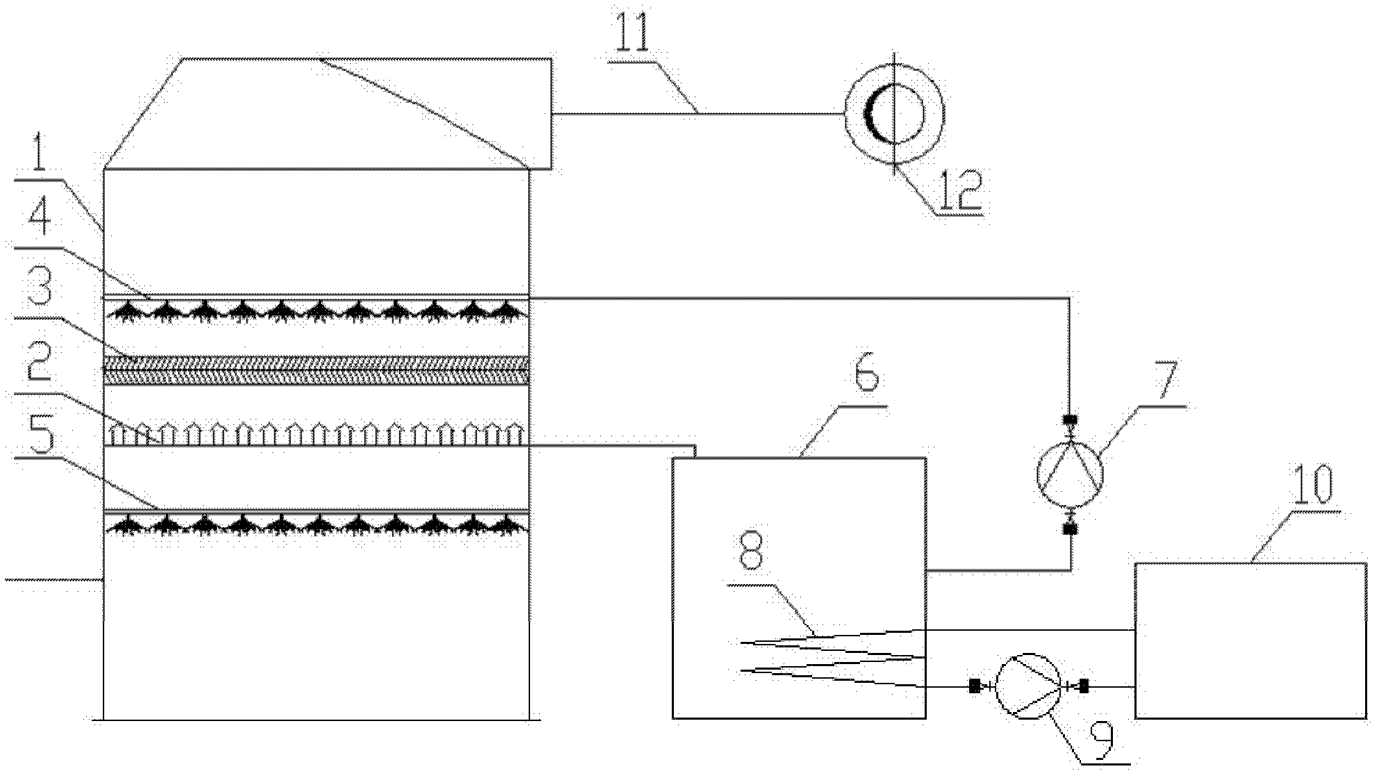
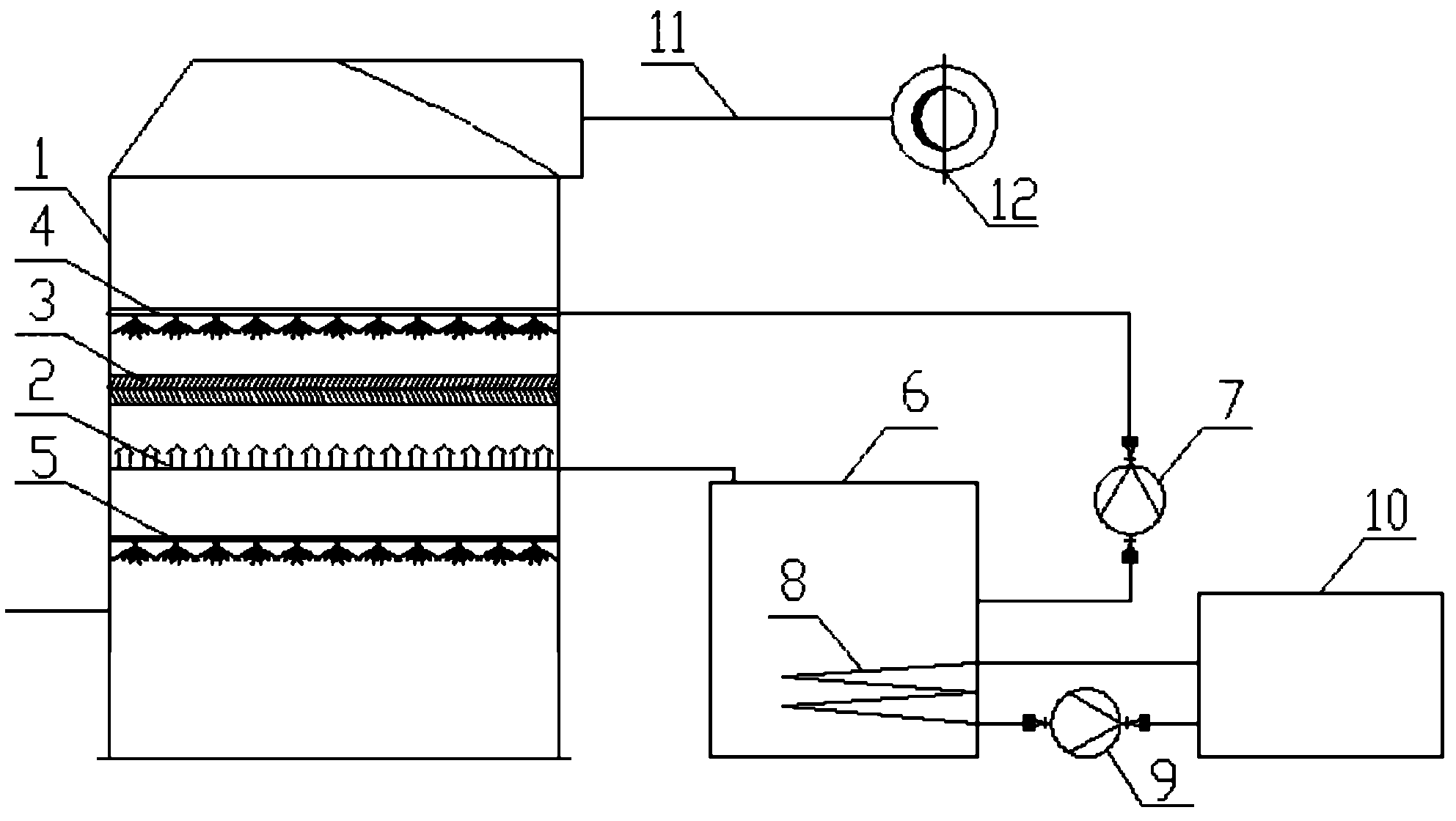
[0016] Such as figure 1 As shown, a clean flue gas recovery treatment device includes: an absorption tower 1, a water-proof air cap water collector 2 arranged from bottom to top in the absorption tower 1, a structured packing layer 3, a cooling spray layer 4 and a demister device (not shown in the figure), and a recycling water circulation device connected to the cooling spray layer 4; the recycling water recycling device includes a recycling water storage device 6, a cooling spray circulating water pump 7, a heat exchanger 8, and a heat exchange circulating pump 9. Closed circulation cooler 10, one side of the recovered water storage device 6 is connected to the cooling spray layer 4 through the cooling spray circulating water pump 7, and the other side of the recovered water storage device 6 is connected to the water-proof air cap water collector 2 The heat exchanger 8 is arranged in the recycled water storage device 6 , and the closed cycle cooler 10 is connected to the rec...

Embodiment 2

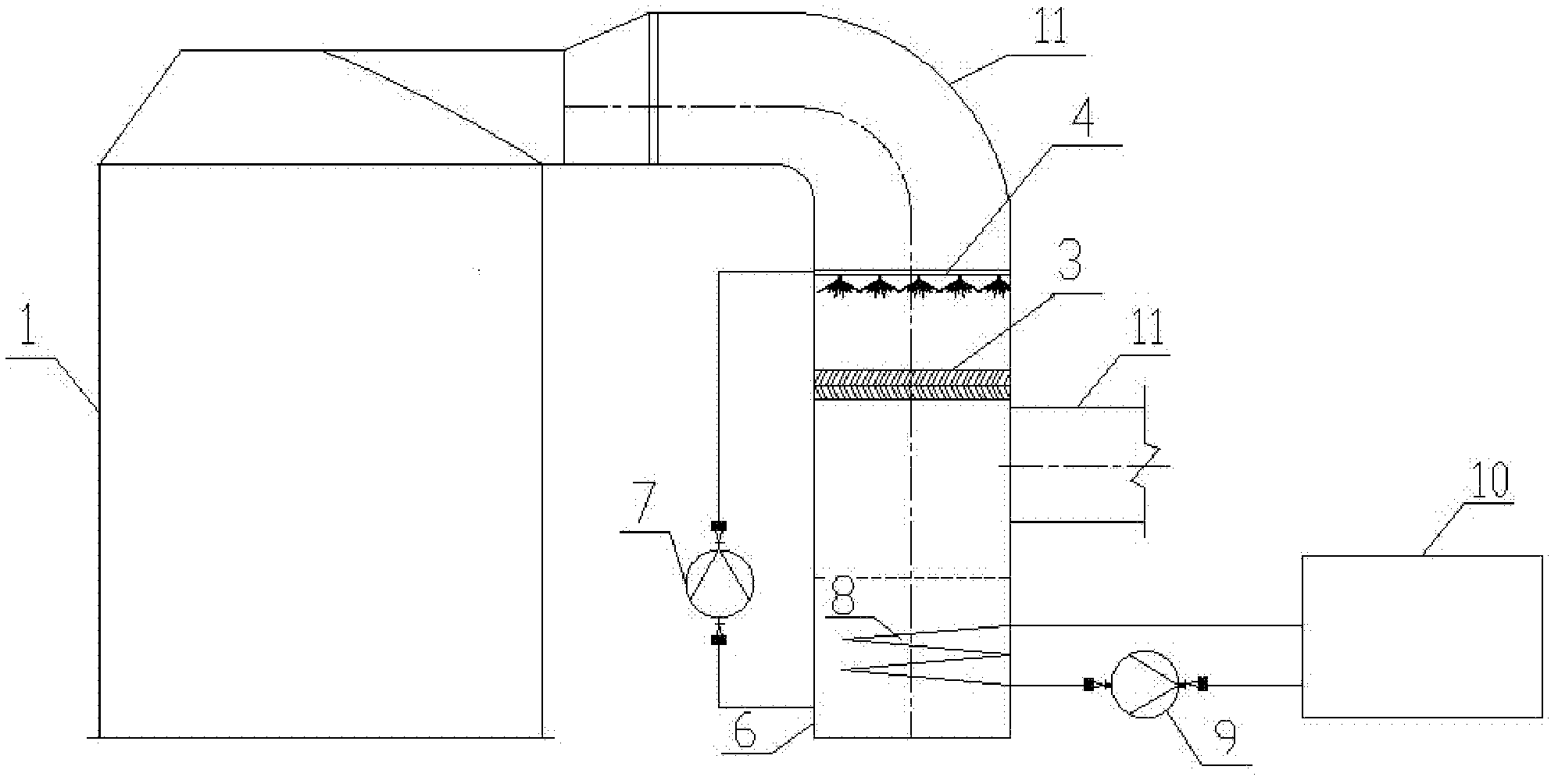
[0019] Such as figure 2 As shown, a clean flue gas recovery treatment device includes: a clean flue 11, a structured packing layer 3 arranged from bottom to top in the clean flue 11, a cooling spray layer 4 and a demister (not shown in the figure) , and a recycling water circulation device connected to the cooling spray layer 4; the recycling water recycling device includes a recycling water storage device 6, a cooling spray circulating water pump 7, a heat exchanger 8, a heat exchange circulating pump 9, and a closed circulation cooler 10. The recovered water storage device 6 is connected to the cooling spray layer 4 through the cooling spray circulating water pump 7, the heat exchanger 8 is set in the recovered water storage device 6, and the closed circulation cooler 10 is connected to the recovery water through the heat exchange circulating pump 9. A water storage device 6 is connected.

[0020] When applying the clean flue gas recovery treatment device of the present in...


PUM


Abstract

The invention relates to a purified flue gas recycling device and in particular relates to a recycling device for purifying flue gas in the field of wet flue gas purification. The purified flue gas recycling device comprises a shell and further comprises a structured packing layer, a cooling spraying layer, a defroster and a recycling water circulator; and the structured packing layer, the cooling spraying layer and the defroster are arranged in the shell from bottom to top, and the recycling water circulator is connected with the cooling spraying layer. Compared with the prior art, the purified flue gas recycling device can be used for effectively solving the problem of recycle of water in purified flue gas, fully utilizing heat carried by the purified flue gas and realizing the recycle of an energy source so as to save a large amount of water resources and achieve a remarkable environmentally-friendly effect, and is suitable for the wet flue gas purification field, such as a limestone-gypsum method, an ammonia method, a double-alkali method and a magnesium method, and is also suitable for being popularized and applied in water removing treatment of other associated purified flue gas-like substances.

Description

technical field [0001] The invention relates to a clean flue gas recycling and processing device, in particular to a clean flue gas recycling and processing device in the field of wet flue gas purification. Background technique [0002] At present, flue gas purification technologies such as wet desulfurization and denitrification are widely used. In the purification process, the common problem is that the water consumption is relatively large. The main manifestation is that after purification, a large amount of water is carried and discharged by the clean flue gas, resulting in huge water Resource waste, especially in water-shortage areas, is more serious. Therefore, it is urgent to solve the problem of recycling water in clean flue gas. Contents of the invention [0003] The purpose of the present invention is to provide a clean flue gas recovery treatment device to solve the problem of water recycling in the clean flue gas, reduce the loss of water resources, and realize...

Claims


Application Information

Patent Timeline
Patent Type & Authority Applications(China)
IPC IPC(8): B01D53/78
Inventor 艾淑艳
Owner 田鹏程
Why Eureka
Try Eureka