Eureka AIR delivers breakthrough ideas for toughest innovation challenges, trusted by R&D personnel around the world.

Steam blackening furnace

A steam and furnace wall technology, applied in cooking furnaces, furnaces, muffle furnaces, etc., can solve the problems of inconsistent thickness of blackened protective layer, unsatisfactory diffusion effect, uneven heating of workpieces, etc., and achieve uniform and dense blackened protective layer thickness , the effect of steam divergence is ideal, and the effect of increasing the heating distance

Inactive Publication Date: 2012-07-25
宁波东方加热设备有限公司
View PDF3 Cites 2 Cited by
  • Summary
  • Abstract
  • Description
  • Claims
  • Application Information

AI Technical Summary

Problems solved by technology

But in actual use, the temperature of the steam entering the inner tank is still not high enough, generally less than 300°C, which cannot be consistent with the temperature of the furnace wall. The temperature of the furnace wall is generally 550°C, which will lead to uneven thermal field in the furnace cavity , that is, the temperature of the position close to the furnace wall in the furnace cavity is high, and the temperature of the position away from the furnace wall is low, the blackening speed of the workpiece is slow, and the thickness of the blackening protective layer of the workpiece is inconsistent
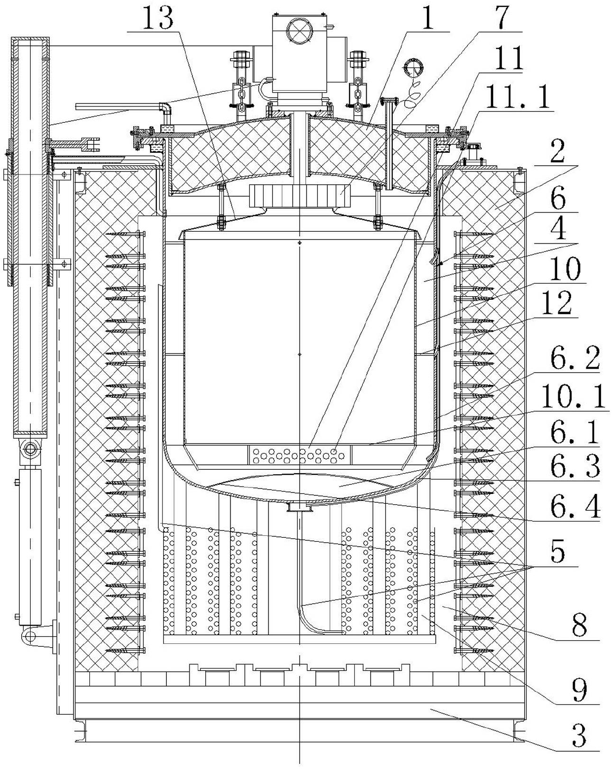
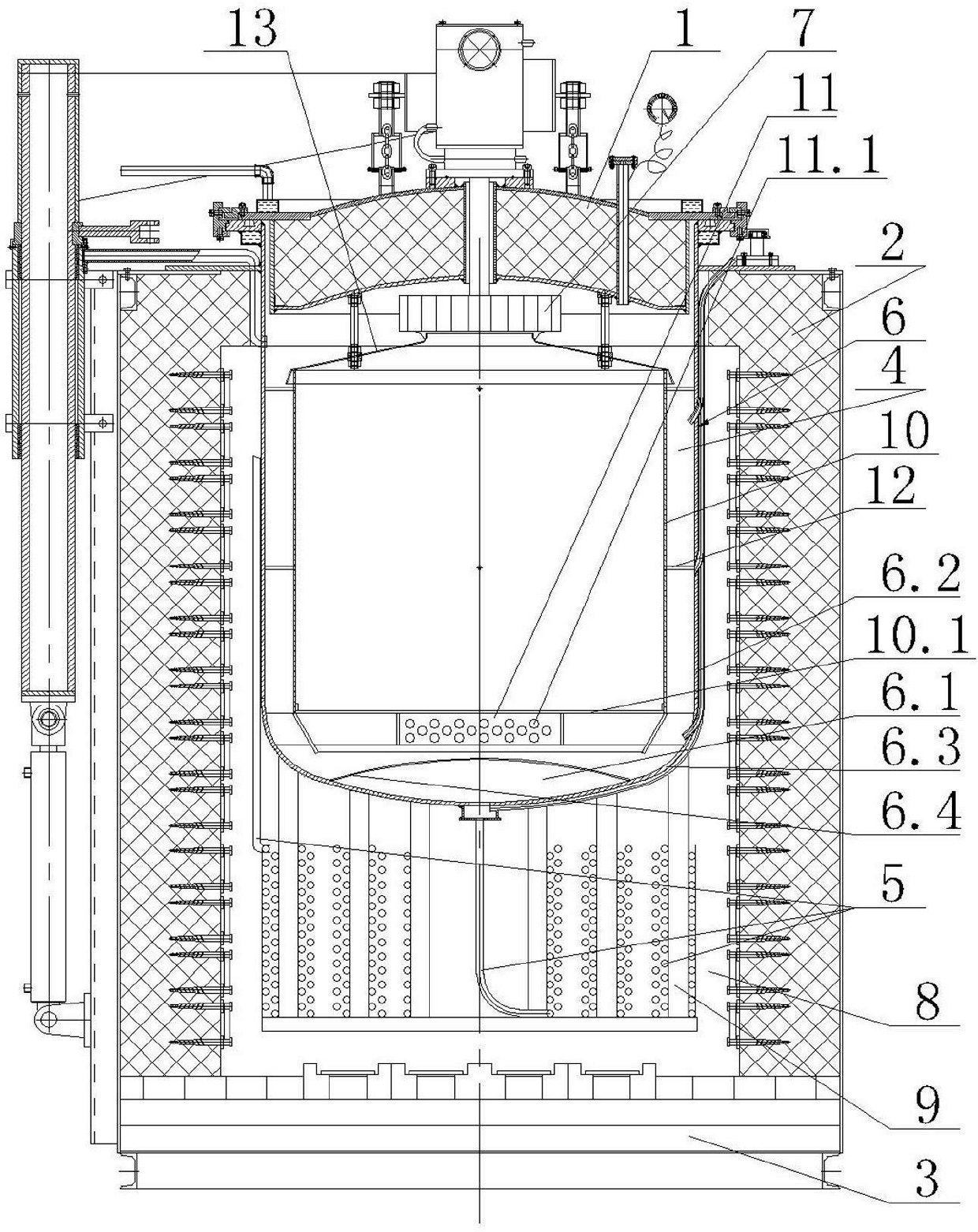
[0004] The outlet of the steam delivery pipe is connected to the inlet of the steam distribution chamber. When the steam diffuses from the steam distribution chamber at the lower part of the inner tank to the upper part of the inner tank, the diffusion effect is not ideal, the steam is not uniformly distributed, and there is more steam above the outlet of the steam delivery pipe. The steam that deviates from the top of the outlet of the steam delivery pipe is less, so that the steam cannot be evenly contacted with the workpiece, the workpiece is heated unevenly, the blackening speed of the workpiece is slow, the thickness of the blackening protective layer of the workpiece is inconsistent, and the blackening effect is poor.
[0005] In order to strengthen the gas convection in the furnace chamber, the lower part of the furnace cover is also equipped with a wind wheel driven by a motor, which drives the gas convection in the furnace chamber through the rotation of the wind wheel. Not ideal, the thermal field in the furnace cavity is uneven, and the quality of the blackened workpiece is still not ideal

Method used


Image

  • Steam blackening furnace
  • Steam blackening furnace

Examples


Embodiment Construction

[0015] The present invention will be further described below in conjunction with the accompanying drawings and specific embodiments.

[0016] Such as figure 1 As shown, the steam blackening furnace of the present invention includes a furnace cover 1, a furnace wall 2, a base 3 and a steam delivery pipe 5 introduced from the outside of the furnace. It can be seen from common sense that the front end of the true gas delivery pipe 5 communicates with the gas pump outside the furnace. The furnace cover 1, the furnace wall 2 and the base 3 surround a synthetic furnace chamber 4. The furnace cavity 4 is provided with an inner container 6, and a heating chamber 8 is arranged below the inner container 6. Specifically, the heating chamber 8 is formed by enclosing the top of the base 3, the lower part of the inner container 6 and the lower part of the furnace wall 2. The top of the base 3 And furnace wall 2 bottoms are all provided with heating unit, and heating unit refers to convent...


PUM


Abstract

The invention discloses a steam blackening furnace, which comprises a furnace lid (1), a furnace wall (2), a base (3) and a steam delivery pipe (5). An inner container (6) is disposed in a furnace chamber (4). A steam diffusion chamber (6.1) is reserved at the lower end of the inner container (6). A heating chamber (8) is reserved below the inner container (6). A plurality of vertical posts (9) are disposed in the heating chamber (8). The middle of the steam delivery pipe (5) is wound on the vertical posts (9) by multiple circles on each post. A guide cylinder (10) is further disposed in the inner container (6). A gap is reserved between the outer wall of the guide cylinder (10) and the inner wall of the inner container (6). A grating plate (10.1) is disposed on the lower portion of the guide cylinder (10). A steam diffusion cylinder (11) is fixed to the lower end face of the grating plate (10.1). The wall of the steam diffusion cylinder (11) is provided with a plurality of diffusion holes (11.1). Steam entering the inner container of the steam blackening furnace is high in temperature, diffusion of the steam from the steam diffusion chamber of the inner container is effective, and the effect of convection of gas in the furnace chamber is ideal.

Description

technical field [0001] The invention relates to the field of heat treatment equipment, in particular to a steam blackening furnace. Background technique [0002] The steam blackening furnace is a furnace body that heat-treats powder metallurgy workpieces to blacken the surface of the workpieces to form a protective layer. It includes a furnace cover, a furnace wall and a base. In the inner container for the workpiece to be heat treated, the furnace cover can be opened and closed for picking and placing the workpiece. [0003] The steam delivery pipe introduced from the outside of the furnace is coiled several times on the outer wall of the inner tank, and then communicates with the steam distribution chamber at the lower part of the inner tank. When the steam spirals along the outer wall of the inner tank, the steam is drawn by the The heating unit heats up step by step, and finally enters the inner tank from the steam distribution chamber. But in actual use, the temperatu...

Claims


Application Information

Patent Timeline
Patent Type & Authority Applications(China)
IPC IPC(8): C23C8/06C23C8/16F27B5/04F27B5/06
Inventor 陈金国陈文芳
Owner 宁波东方加热设备有限公司
Why Eureka
Eureka Blog
Learn More