Repetition frequency compact pulse multiplier based on Fitch circuit
A repetition frequency and multiplier technology, applied in the direction of conversion equipment without intermediate conversion to AC, can solve the problems of not many primary windings, large volume of pulse transformers, unfavorable miniaturization of pulse sources, etc.
- Summary
- Abstract
- Description
- Claims
- Application Information
AI Technical Summary
Problems solved by technology
Method used
Image
Examples
Embodiment 1
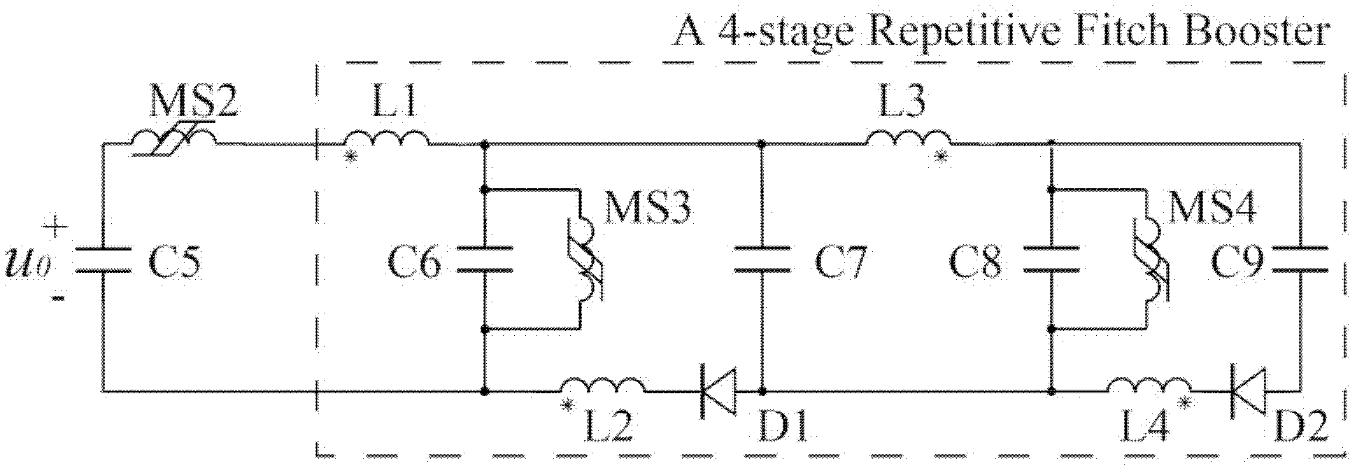
[0028] A four-stage pulse multiplier is designed, and its circuit diagram is shown in the attached image 3 :
[0029] 1. Four charging capacitors C6-C9 are placed side by side, and the upper end of C6 and C7, the lower end of C7 and C8, and the upper end of C8 and C9 are connected.
[0030] 2. The unconnected pins of adjacent capacitors (that is, the lower end of C6 and the upper end of C7, the lower end of C7 and the upper end of C8, the lower end of C8 and the upper end of C9) are connected together through coupling inductors. According to the terminal connection of the same name as shown in the figure, when the capacitor is charged, the sum of the current flowing through the coupled inductor is zero, which can be explained as follows. Assume that the charging waveform of each capacitor is consistent during charging, so its charging current i is the same at any moment. According to the coupled inductor connection in the figure, it can be obtained: 1 current i L1 = 4i.i ...
Embodiment 2
[0038] Such as Figure 4 As shown, the structure of the five-stage pulse multiplier is equivalent to the parallel connection of the final capacitor of the four-stage pulse multiplier, the series coupling of the inductor L18 and the capacitor C24, and the capacitor C24 is connected in parallel with the magnetic switch M13. In addition, in order to ensure that the net current flowing into the coupled inductor is zero during charging, L15 is connected in series with the coupled inductor L16 with the same number of turns, and the coupling direction of L14 and L17 is opposite to that of the four-stage pulse multiplier.
Embodiment 3
[0040] Such as Figure 5 As shown, it is an eight-stage pulse multiplier. Compared with a four-stage pulse multiplier, the structure of an eight-stage pulse multiplier is equivalent to two four-stage pulse multipliers cascaded. The coupling direction of L5 and L11 in the above figure is taken as opposite. The arrangement of the coupled inductors is to ensure that the net current flowing into the coupled inductors is zero when the eight-stage pulse multiplier is charging, and the coupling directions of the upper row of coupled inductors are consistent.
[0041] According to the above design method, pulse multipliers with different stages (N capacitors are N stages) can be designed, and they have the dual effects of pulse amplitude multiplication and rising edge compression.
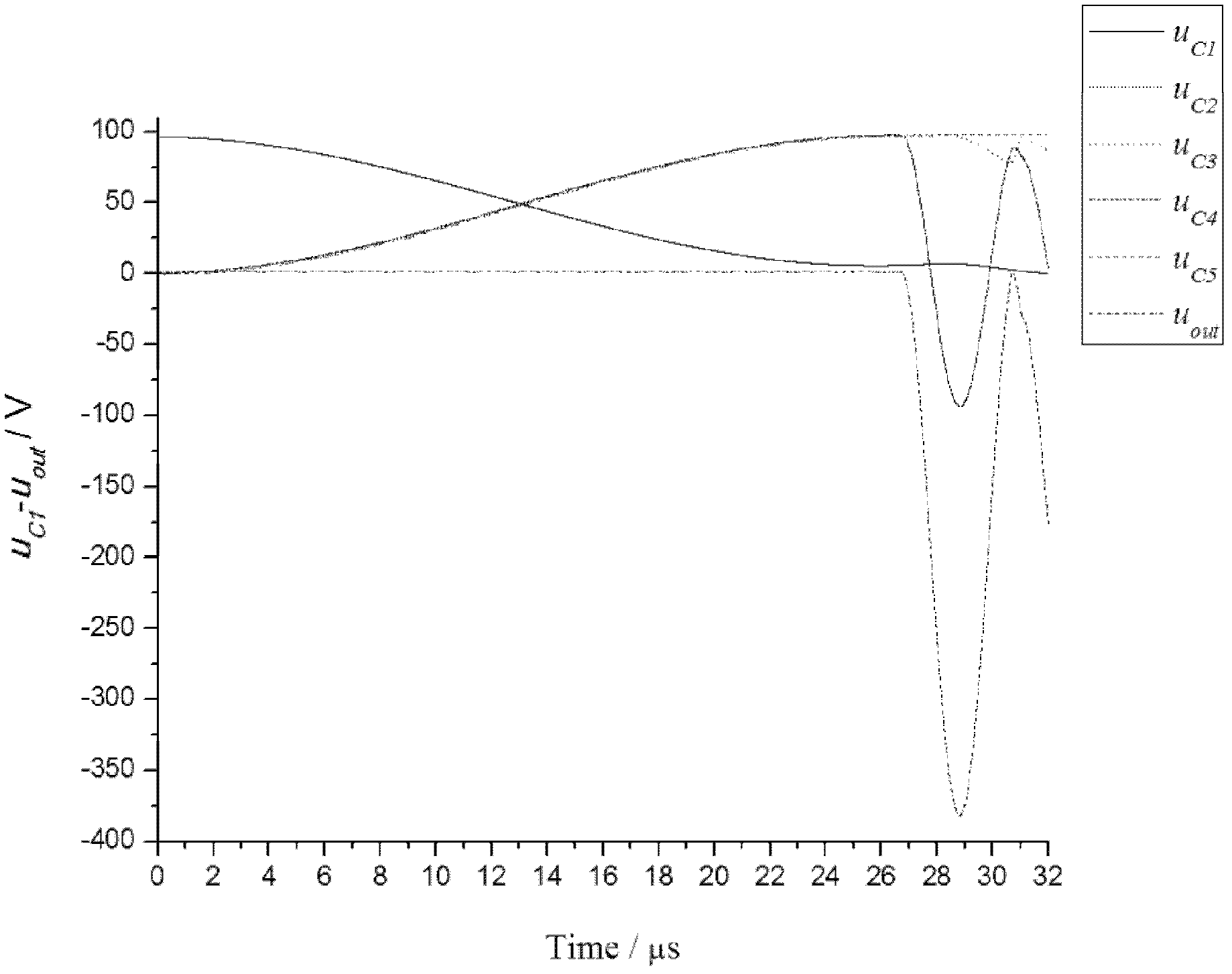
[0042] Using the Matlab Simulink module to simulate the circuit of the four-stage pulse multiplier, the capacitor voltages and output voltage waveforms of each stage are obtained, as shown in the attached...
PUM
 Abstract
Description
Claims
Application Information
 - R&D
- Intellectual Property
- Life Sciences
- Materials
- Tech Scout
- Unparalleled Data Quality
- Higher Quality Content
- 60% Fewer Hallucinations
Browse by: Latest US Patents, China's latest patents, Technical Efficacy Thesaurus, Application Domain, Technology Topic, Popular Technical Reports.
© 2025 PatSnap. All rights reserved.Legal|Privacy policy|Modern Slavery Act Transparency Statement|Sitemap|About US| Contact US: help@patsnap.com


