Device for rapidly treating ring formation of rotary kiln and method
What is Al technical title?
Al technical title is built by PatSnap Al team. It summarizes the technical point description of the patent document.
A processing device and rotary kiln technology, which is applied in the chemical industry, building materials, refractory rotary kiln, and metallurgy fields. It can solve the problems of lack of control devices, inconvenient operation, and small impact force, so as to achieve direct energy transmission, improve ring cleaning efficiency, The effect of high impact force
Active Publication Date: 2013-11-27
GONGYI XIAOYI JINLI MECHANICAL EQUIP MFG FACTORY
View PDF6 Cites 0 Cited by
Summary
Abstract
Description
Claims
Application Information
AI Technical Summary
This helps you quickly interpret patents by identifying the three key elements:
Problems solved by technology
Method used
Benefits of technology
Problems solved by technology
With this structure, although the kiln cleaning work can be automatically completed without stopping the furnace, the energy consumption can be reduced, and the conversion rate of the material can be improved, but there are still many defects. The impact force is small, and the driving device of the poking rod is located below the poking rod, acting on the poking rod through the hanger, driving the poking rod to move back and forth under the premise of overcoming the self-weight of the poking rod, the energy loss is large, the impact force is reduced, and it takes time to clean the kiln Longer and less efficient; second, the overall length of the poking rod is long, and the cost of replacing the whole poking rod after long-term use and damage is high; third, there is a lack of control devices to control the kiln car's forward, backward and even speed Fast and slow, inconvenient to operate
Method used
Image
Click on the blue label to locate the original text in one second.
Reading with bidirectional positioning of images and text.
Examples
Embodiment 1
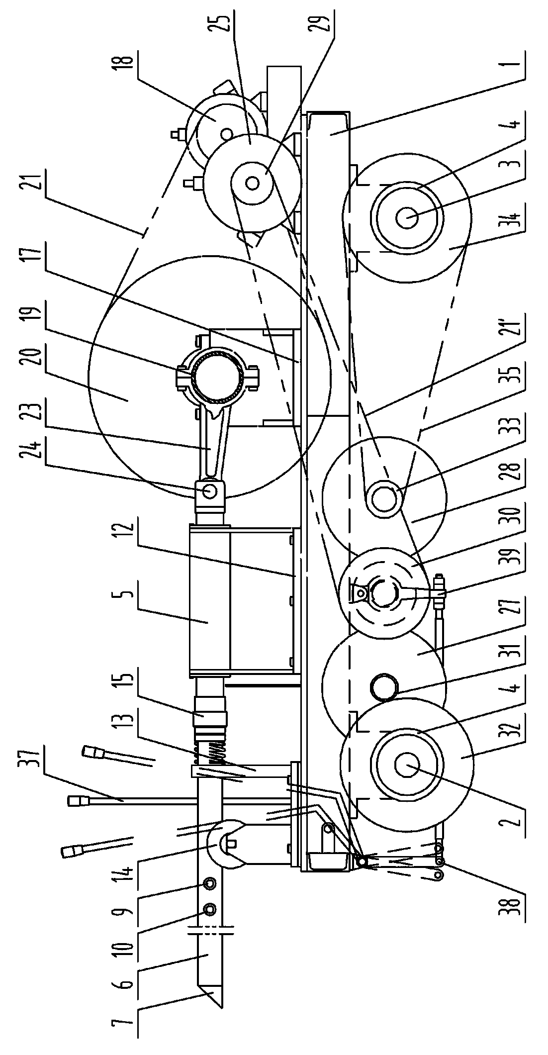
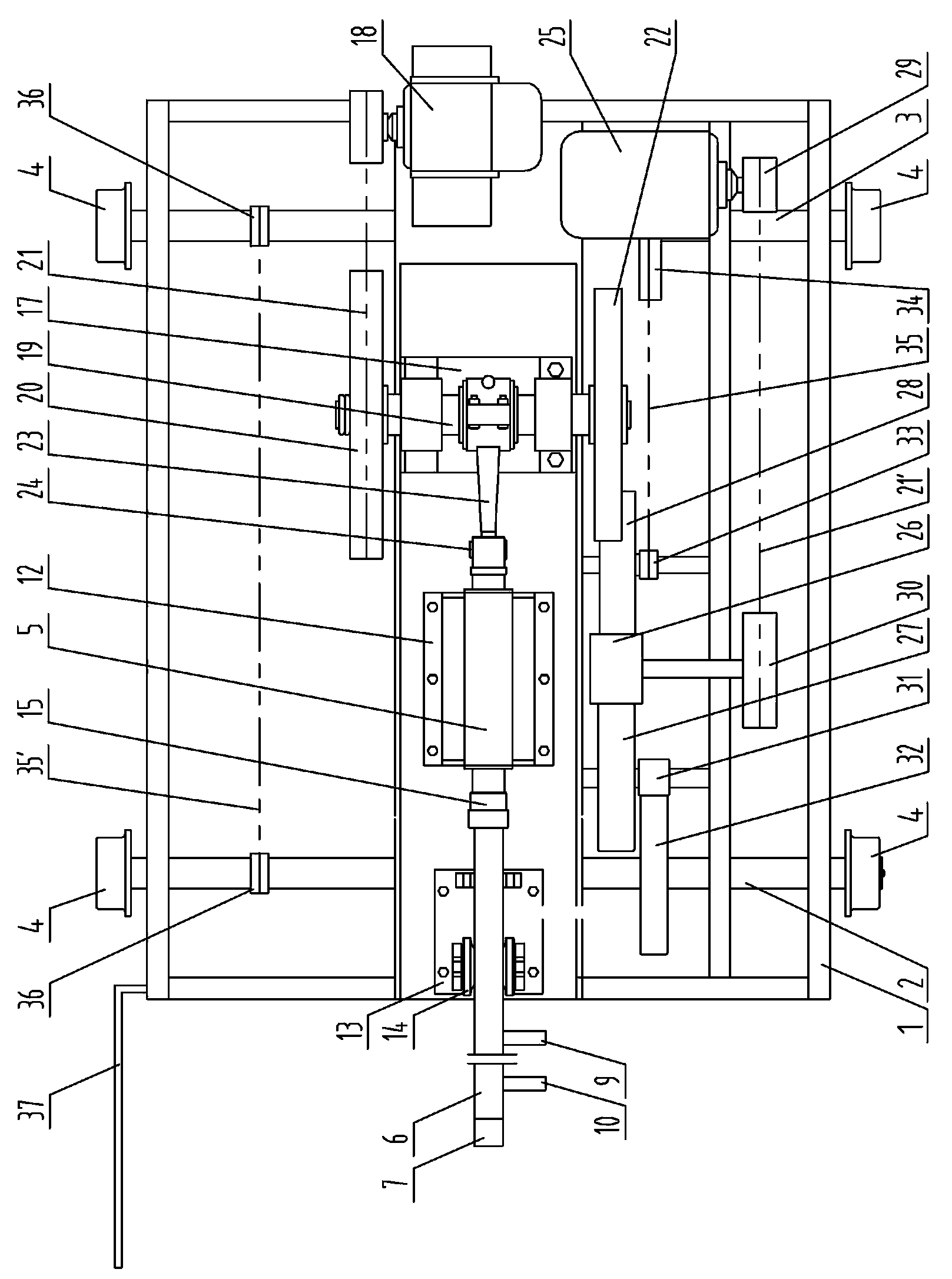
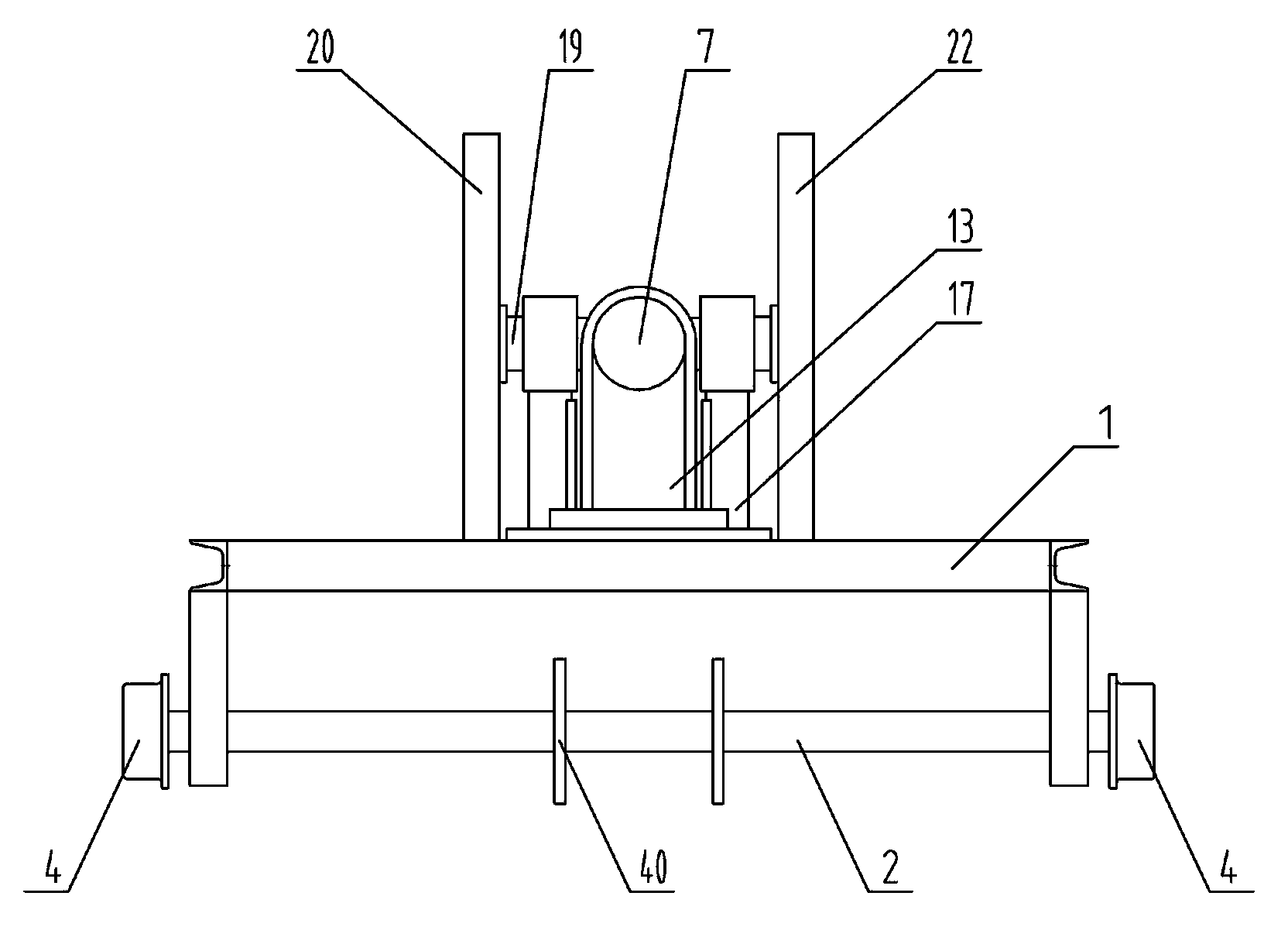
[0032] Working principle of the present invention:
[0033] The working principle of the present invention is similar to the working condition when the impact drill drills the inner wall, that is, the shovel head 7 and the shovel rod 6 extend into the kiln from the kiln head or kiln tail of the rotary kiln, and can reach the part formed by the kiln ring and the thick kiln skin , the axial trajectory of the shovel rod 6 and the shovel head 7 is roughly parallel to the axis of the rotary kiln shell, the shovel rod 6 and the shovel head 7 move rapidly under the impact, and the rotary kiln shell, the kiln skin and the kiln ring are used to rotate, The kinetic energy of the impact shovel head 7 acts on the bottom of the rotary kiln rings and thick kiln skins that are relatively stationary in the radial direction, and the bottom layer of the rotary kiln rings and thick kiln skins is shaved; because the surface of the rotary kiln rings and kiln skins is soft at high temperatures Crun...
Embodiment 2
[0038] The above descriptions are only illustrative specific implementations of the present invention, and are not intended to limit the scope of the present invention. Any equivalent changes and modifications made by those skilled in the art without departing from the concepts and principles of the present invention are acceptable. Should belong to the protection scope of the present invention.
PUM
Abstract
The invention belongs to the technical field of rotary kilns for metallurgy, building materials, chemical engineering and refractory materials, and particularly relates to a device for rapidly treating ring formation of a rotary kiln and a method. The device comprises a kiln car, an impact bar, an impact bar support device, an impact bar driving device, a kiln car driving device and an operating device, the impact bar, the impact bar support device and the impact bar driving device are arranged on the kiln car, the kiln car consists of a frame, a front axle, a rear axle and wheels mounted on two sides of the front axle and the rear axle, a hollow shovel rod is movably connected to the front end of the impact bar and fixed onto the kiln car by a shovel rod support device, a shovel head is fixed to the front end of the shovel rod, a cooling water pipe is fixedly sleeved in the shovel rod, a water inlet of the cooling water pipe is fixed to the rear end of the shovel rod, a water outlet pipe is additionally fixedly disposed at the rear end of the shovel rod and communicated with the inside of the shovel rod, and an annular plug is disposed between the inner wall of the shovel rod on the rear side of the water outlet pipe and the outer wall of the cooling water pipe. Impact force for automatically removing rings is high, the device is high in efficiency, low in service cost and convenient in operation, simultaneously, energy consumption can be reduced, sintering conversion rate of materials is improved, yield of the rotary kiln is increased, economic benefit is remarkable, and the device is suitable for popularization and implementation.
Description
technical field [0001] The invention belongs to the technical field of metallurgy, building materials, chemical industry, and refractory material rotary kiln, and specifically relates to a rotary kiln fast processing device and method for kiln system of refractory material, chemical industry, metallurgy, and building material production line in domestic calcination, sintering, and roasting industries . Background technique [0002] As we all know, during the use of the rotary kiln in the kiln system of the domestic calcination, sintering and roasting industry refractories, chemical industry, metallurgy and building materials production line, there are common problems such as uneven rotary kiln skin, thick rotary kiln skin, long rotary kiln skin, Chronic problems such as ring formation, nodules, egg formation, and large and small balls in the rotary kiln lead to uneven red kiln and material layers in the rotary kiln, increased resistance in the rotary kiln system, and reduced...
Claims
Application Information
Patent Timeline
Application Date:The date an application was filed.
Publication Date:The date a patent or application was officially published.
First Publication Date:The earliest publication date of a patent with the same application number.
Issue Date:Publication date of the patent grant document.
PCT Entry Date:The Entry date of PCT National Phase.
Estimated Expiry Date:The statutory expiry date of a patent right according to the Patent Law, and it is the longest term of protection that the patent right can achieve without the termination of the patent right due to other reasons(Term extension factor has been taken into account ).
Invalid Date:Actual expiry date is based on effective date or publication date of legal transaction data of invalid patent.