
Microprobe scratching machining method with force feedback control function for manufacturing microstructure

A processing method and micro-probe technology, applied in the directions of micro-structure technology, micro-structure device, manufacturing micro-structure device, etc., can solve the problems of inability to meet, low processing efficiency, small processing range, etc., and achieve shape precision elimination and installation. The effect of precision error elimination and low cost

Active Publication Date: 2012-07-18
HARBIN INST OF TECH
View PDF7 Cites 7 Cited by
  • Summary
  • Abstract
  • Description
  • Claims
  • Application Information

AI Technical Summary

Problems solved by technology

However, there are currently two problems with the use of AFM system for nanomechanical scribing processing: (1) The processing range is small and the processing efficiency is low
At present, it cannot meet the practical needs of complex microstructures such as micron-scale grooves widely used in micro-optics, MEMS and other fields.

Method used


Image

  • Microprobe scratching machining method with force feedback control function for manufacturing microstructure
  • Microprobe scratching machining method with force feedback control function for manufacturing microstructure
  • Microprobe scratching machining method with force feedback control function for manufacturing microstructure

Examples


specific Embodiment approach 1

[0020] Embodiment 1: A microprobe marking processing method with force feedback control for microstructure manufacturing, the processing method is realized by the following steps:

[0021] Step 1: The microprobe tool automatically approaches the surface of the workpiece (this process is realized by detecting the force value received by the microprobe tool 1 in the Z direction, and controlling the stepping motor to realize the rough feed of the Z direction coarse motion table 2 and control the piezoelectric ceramics to drive the precision feed of the micro-motion table 3 in the Z direction to achieve the set initial force value, thereby realizing the initial contact between the microprobe tool 1 and the surface of the workpiece 4);

[0022] First place the workpiece 4 on the precision table 5 in the X-Y direction, and make the microprobe tool 1 automatically approach the surface of the workpiece 4 and maintain a constant force F according to the set initial force value, referred...

specific Embodiment approach 2

[0029] Specific embodiment two: what this embodiment provides is a kind of microprobe marking processing device with force feedback control, see Figure 5 , the device mainly includes a Z-direction support plate 11, a support platform 12, a computer 13,

[0030] Z-direction coarse motion table 2, Z-direction micro-motion table 3, force sensor 6, microprobe tool 1, X-Y direction precision table 5 and UMAC control unit 10; where:

[0031] The X-Y direction precision workbench 5 is set on the support platform 12, the workpiece 4 is set on the X-Y direction precision workbench 5, and the lower end of the Z-direction support plate 11 is fixed on the support platform 12; the UMAC control unit 10 sends two analog signals, Control the movement of the Z-direction coarse motion table 2 and the Z-direction micro-motion table 3 respectively. The communication between the computer 13 and the UMAC control unit 10 is realized by network cable transmission, and the computer control software sen...

Embodiment 1

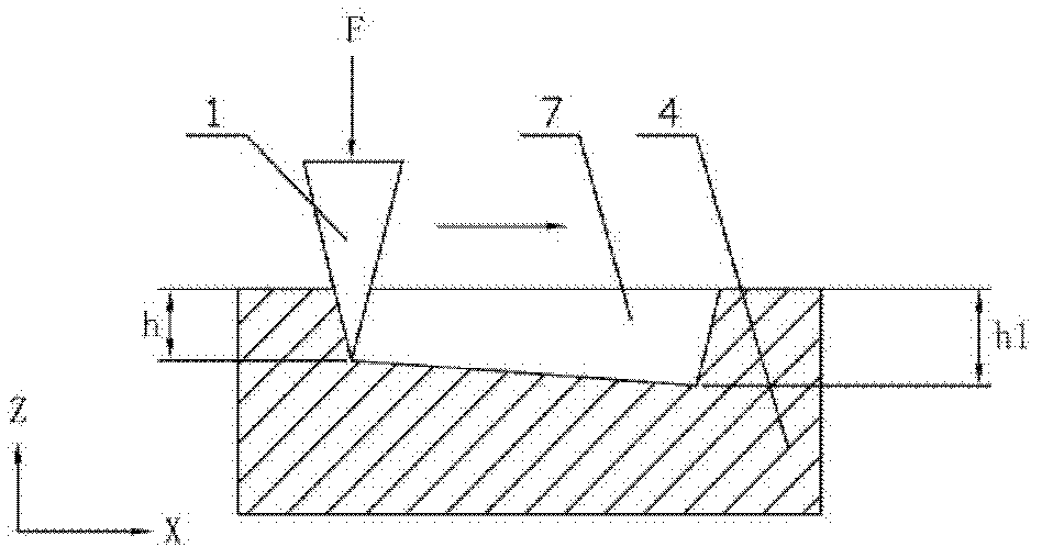
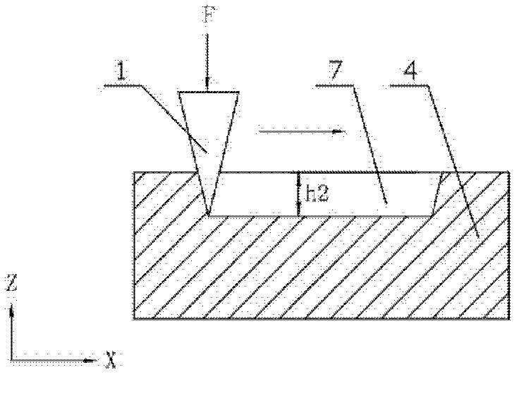
[0038] Example 1: Set the initial value of the constant force to 17mN, process on the surface of the polymer polycarbonate (PC) material workpiece, the scoring length is 2000μm, the scoring speed is 0.02mm / s, and the marking is measured every 250μm stroke depth, Kp=18000, Ki=36500, from Figure 4 It is not difficult to see from the relationship curve between processing depth and scoring length under the medium-force open-loop state that the processing depth of the micro-groove 7 decreases gradually with the increase of the scoring length; Figure 4 It is not difficult to see the relationship curve between processing depth and scoring length under the medium-force closed-loop state. Although the relationship curve is not completely a straight line (within the experimental error range), there is no tendency to increase with the scoring length. The experimental results verify the feasibility of this method.


PUM


Abstract

The invention provides a microprobe scratching machining method with a force feedback control function for manufacturing a microstructure, belongs to the technical field of micro-nano structure machining, and can achieve the low-cost and high-precision machining to complex microstructures such as micro scale grooves and the like. The method comprises the following steps: firstly, a workpiece is placed on a precise working table in the X-Y direction, a microprobe cutter is ensured to automatically approach to the surface of the workpiece and maintain a constant force F according to a set force initial value (set value), the initial value of the constant force F is 5 to 20 mN, after the microprobe cutter is in contact with the surface of the workpiece directly, the microprobe cutter starts to conduct the scratching machining, a force closed loop control module is started, the microprobe cutter moves up and down on a micro-motion working table in the Z-direction to achieve the in-time closed loop control to a vertical force, the precise working table in the X-Y direction drives the workpiece to precisely move to achieve the processing to the micro groove structure, after the micro groove structure is processed, the force closed loop control is finished, the microprobe cutter is driven upwards by a coarse-motion working table in the Z-direction to be separated from the surface of the workpiece, and the processing is over. The invention is used for processing the micro groove structure of the workpiece.

Description

technical field [0001] The invention belongs to the technical field of micro-nano structure processing, in particular to a micro-probe marking processing method with force feedback control. Background technique [0002] The processing technology based on mechanical removal has been widely studied because of its simple processing equipment, the ability to process complex three-dimensional and even curved microstructures, and low-cost processing. For example, the use of ultra-precision diamond turning technology has been able to process complex surface shapes and precision structures. However, as the processing structure is reduced to the micron scale, it is difficult to process high-precision microstructures with traditional ultra-precision machine tools due to the limitation of tool size and manufacturing accuracy of machine tool components. At the same time, nanomechanical scribing technology based on AFM microprobes is widely used in the field of nanostructure fabrication...

Claims


Application Information

Patent Timeline
IPC IPC(8): B81C1/00
Inventor 闫永达胡振江赵学森周起琛孙涛董申
Owner HARBIN INST OF TECH
Learn More