
Motor control device

A technology for control devices and electric motors, applied in the direction of electronic commutation motor control, single motor speed/torque control, current controller, etc., can solve problems such as increased vibration and noise, deterioration of efficiency, and out of step

Inactive Publication Date: 2012-07-11
SHARP KK
View PDF4 Cites 9 Cited by
  • Summary
  • Abstract
  • Description
  • Claims
  • Application Information

AI Technical Summary

Problems solved by technology

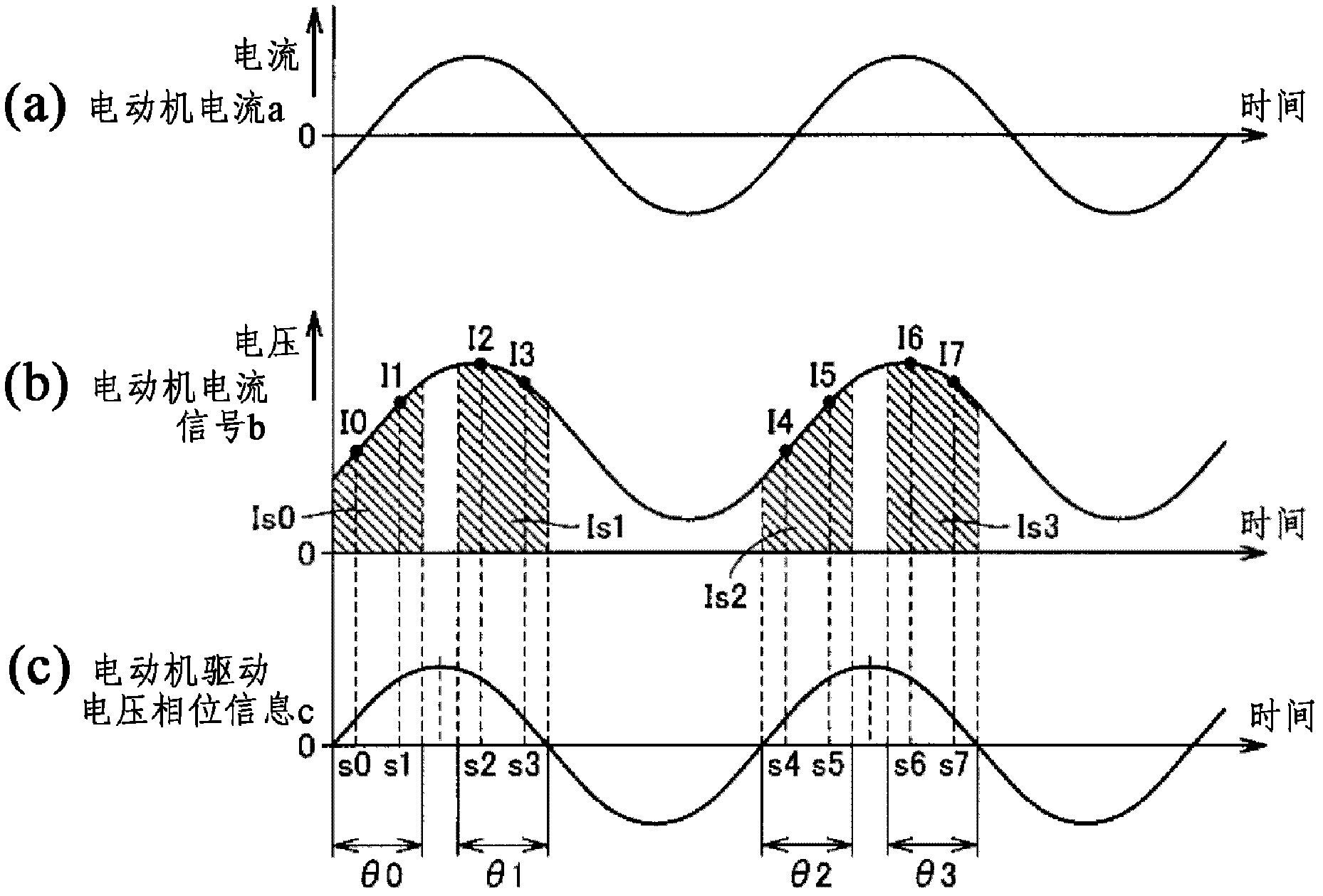
Thus, if the frequency of the inverter is close to the frequency of the fluctuation of the DC voltage, then as Figure 12 As shown in (b) of the inverter, the motor current on the output side of the inverter produces large pulsations, making the rotation of the motor unstable, resulting in increased vibration and noise, deterioration of efficiency, and in the worst case, even cause out of step and stop

Method used


Image

  • Motor control device
  • Motor control device
  • Motor control device

Examples


Embodiment Construction

[0061] Embodiments of the present invention will be described below with reference to the drawings. In the following description, the same components are given the same reference numerals. Their names and functions are also the same. Therefore, detailed descriptions of them will not be repeated.

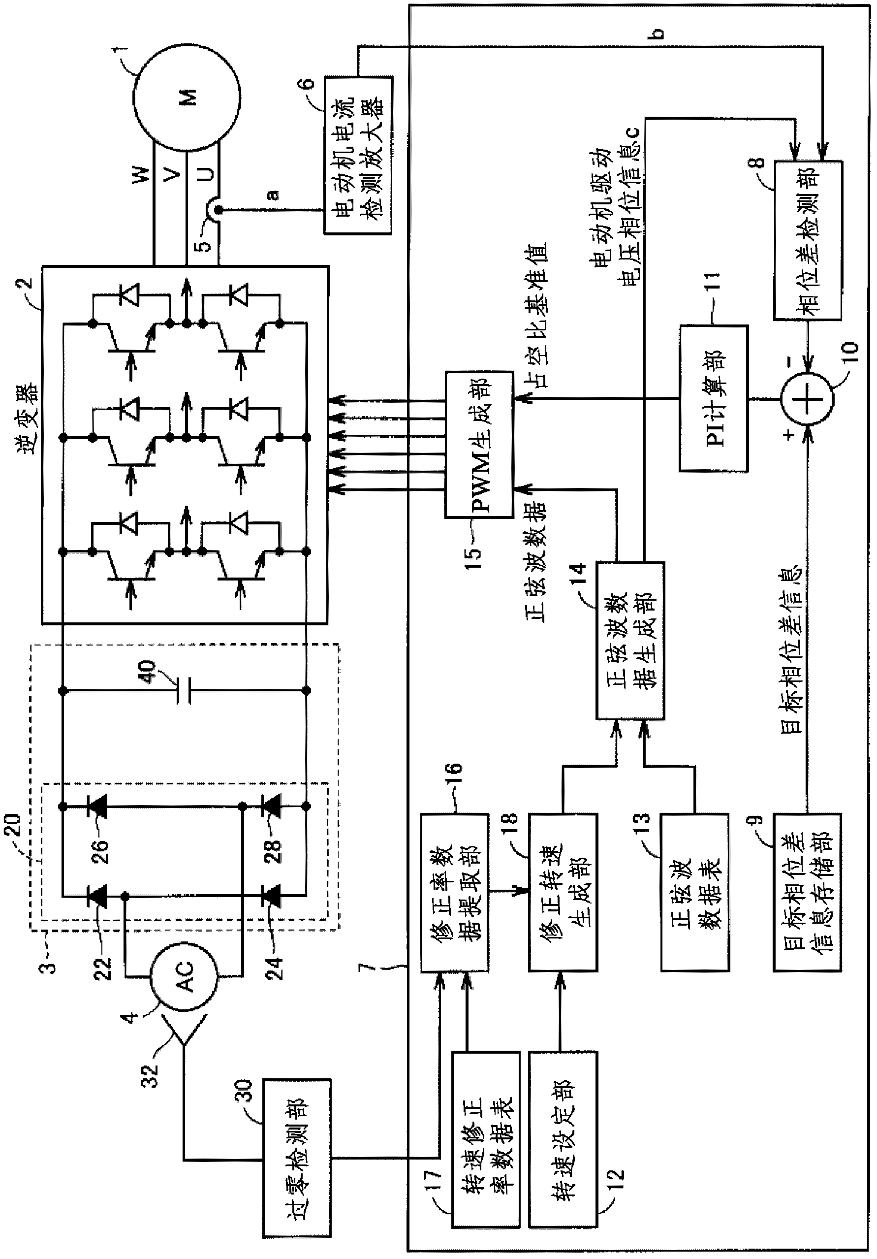
[0062]use figure 1 , a block diagram of a motor control device according to an embodiment of the present invention will be described.

[0063] refer to figure 1 , The motor control device includes: synchronous motor 1, the stator is provided with multi-phase (three-phase) coils, and the rotor is provided with permanent magnets; inverter 2; conversion circuit 3; AC power supply 4; current sensor 5; motor current detection amplifier 6; A zero-cross detection unit 30; a voltage sensor 32; and a controller 7 as a microcomputer.

[0064] Synchronous motor 1 is driven by inverter 2 , and DC voltage obtained by converting AC voltage from AC power supply 4 is supplied to inverter 2 fr...


PUM


Abstract

A zero-cross detecting unit (30) monitors an AC voltage detected by a voltage sensor (32), generates a zero-cross point signal when the AC voltage strides across zero volt, and sends the signal to a controller (7). A rotational speed setting unit (12) of the controller (7) sets a command for a rotational speed that will become the target of a synchronous motor (1). A rotational speed correction factor data table (17) has stored therein correction factor data for target rotational speeds. A correction factor data extracting unit (16) extracts correction factor data corresponding to the elapsed time of the zero-cross point signal that was generated from the rotational speed correction factor data table by the zero-cross detecting unit (30), and outputs the correction factor data to a correction rotational speed generating unit (18). The correction rotational speed generating unit (18) corrects the rotational speed set by the rotational speed setting unit (12), according to the extracted correction factor data, and outputs the corrected rotational speed to a sine wave data creating unit (14).

Description

technical field [0001] The present invention relates to a motor control device, for example, to a motor control device capable of driving a synchronous motor having a multi-phase coil without using a sensor. Background technique [0002] Conventionally, when driving a synchronous motor having multi-phase coils, it is very important to optimize the timing of energization, that is, to pass the motor current to the motor rotor and to apply voltage to the coil terminals at appropriate timing. In order to detect the reference of the energization timing, there are various methods such as a method of detecting a counter electromotive force, a method of detecting a phase of a zero-crossing current, and the like. [0003] For example, in the so-called sensorless drive that controls the drive of the motor without using the motor rotor position sensor, there is a detection method in which when the motor coil is energized, the motor coil terminal detects that the motor coil is rotated. ...

Claims


Application Information

Patent Timeline
Patent Type & Authority Applications(China)
IPC IPC(8): H02P6/18H02P6/06H02P6/08H02P6/182H02P6/28
CPCH02P6/10
Inventor 龟山浩幸
Owner SHARP KK
Learn More