Hydraulic circuit with accumulator

a technology of hydraulic circuit and accumulator, which is applied in the direction of brake cylinders, servomotors, braking systems, etc., can solve the problems of restricting the supply of hydraulic fluid from the hydraulic fluid chamber of the accumulator to the hydraulic actuator, and achieve the effect of reducing the discomfort caused by the pulsation of hydraulic fluid in the hydraulic actuator, and reducing the size of the hydraulic circui

Inactive Publication Date: 2006-12-26
ADVICS CO LTD
View PDF18 Cites 8 Cited by
  • Summary
  • Abstract
  • Description
  • Claims
  • Application Information

AI Technical Summary

Benefits of technology

[0006]The present invention was made in order to solve the above-described problem, and an object of the present invention is to provide a hydraulic circuit which employs an accumulator that operates when the pressure in a hydraulic fluid chamber is at least a set pressure and which can reduce pulsations of hydraulic fluid discharged from a hydraulic pump in a transient period until the pressure in the hydraulic fluid chamber reaches the set pressure.
[0008]In a hydraulic circuit according to the present invention, a valve mechanism is provided which restricts the supply of hydraulic fluid to a hydraulic actuator when the pressure in a hydraulic fluid chamber is less than a set pressure and which releases the restriction on the supply of hydraulic fluid to the hydraulic actuator when the pressure in the hydraulic fluid chamber is at least the set pressure. Therefore, in a transient period until the pressure in the hydraulic fluid chamber reaches the set pressure, the supply of hydraulic fluid from the hydraulic fluid chamber of the accumulator to the hydraulic actuator is restricted by the valve mechanism. Accordingly, the transmission of pulsations of the hydraulic fluid from the hydraulic fluid chamber of the accumulator to the hydraulic actuator are restricted, and the discomfort caused by pulsations of the hydraulic fluid in the hydraulic actuator can be decreased.
[0009]In addition, when the pressure in the hydraulic fluid chamber becomes at least the set pressure, the accumulator operates, and pulsations of the hydraulic fluid which is discharged from the hydraulic pump are decreased, so the discomfort caused by pulsations of the hydraulic fluid in the hydraulic actuator can be decreased. Moreover, at this time, the valve mechanism releases the restriction on the supply of hydraulic fluid from the accumulator to the hydraulic actuator, so a necessary and sufficient amount of hydraulic fluid can be supplied from the accumulator to the hydraulic actuator.
[0010]According to one form of the invention, the valve mechanism is installed inside the accumulator, so the structure of the hydraulic circuit can be made more compact compared to the case in which the valve mechanism is installed outside the accumulator.

Problems solved by technology

Therefore, in a transient period until the pressure in the hydraulic fluid chamber reaches the set pressure, the supply of hydraulic fluid from the hydraulic fluid chamber of the accumulator to the hydraulic actuator is restricted by the valve mechanism.

Method used


Image

  • Hydraulic circuit with accumulator
  • Hydraulic circuit with accumulator
  • Hydraulic circuit with accumulator

Examples


first embodiment

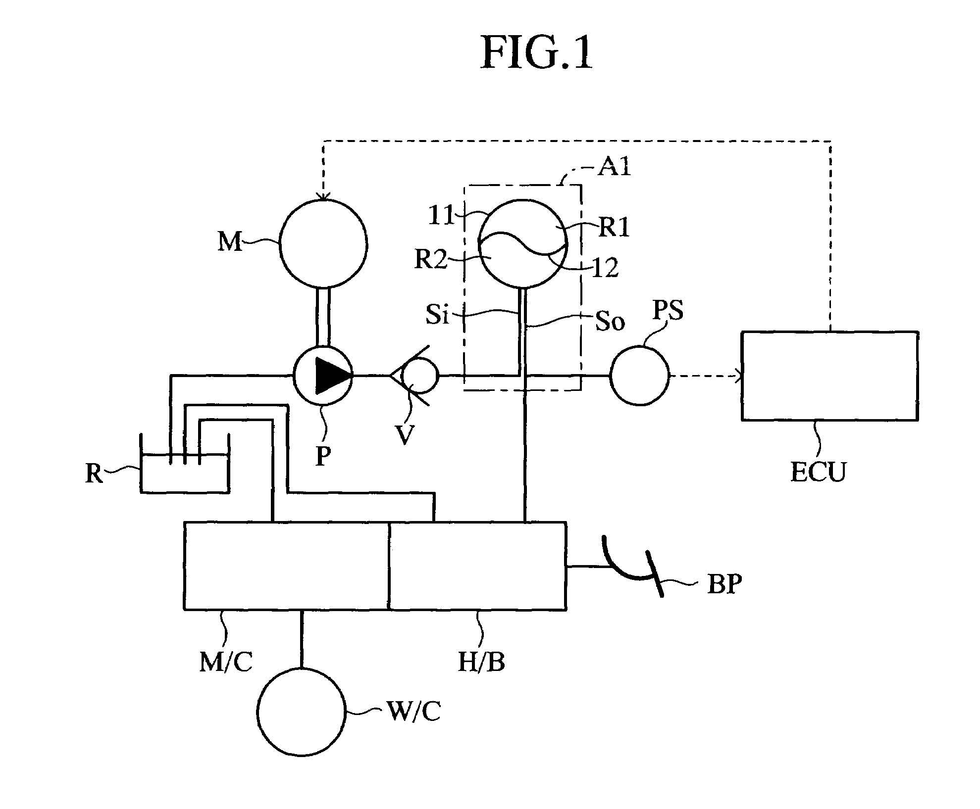
[0026]Embodiments of the present invention will be described while referring to the accompanying drawings. FIGS. 1–3 schematically illustrate the present invention employed as brake hydraulic circuit for an automobile. In this embodiment, a hydraulic fluid from a hydraulic pump P which is driven by an electric motor M passes through a check valve V and is stored in an accumulator A1. From the accumulator A1, the hydraulic fluid is supplied to a hydraulic booster H / B as a hydraulic actuator, which operates in response to the pressing of a brake pedal BP to provide a supplemental force for operation of a master cylinder M / C. The hydraulic fluid which is not needed by the hydraulic booster H / B is returned to a reservoir R.

[0027]In this first embodiment, the hydraulic pump P is connected to the reservoir R, and the master cylinder M / C is connected to the reservoir R and to a plurality of wheel cylinders W / C for the brakes of the automobile. The operation of the electric motor M is contr...

second embodiment

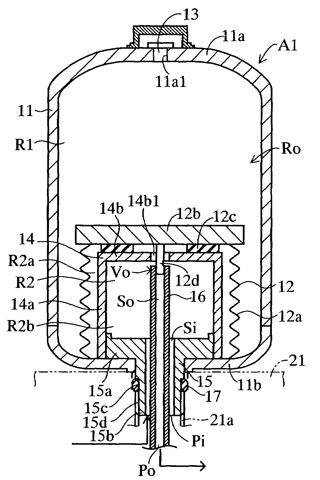
[0042]The accumulator A2 of the second embodiment shown in FIG. 5 includes a shell 111 which forms a pressure space Ro and a bellows 112 disposed inside the pressure space Ro. The shell 111 comprises upper and lower portions which are connected to each other in a gas-tight manner. A plug 113 which seals a gas charging opening 111a1 in a gas-tight manner is installed on an upper wall 111a of the shell 111.

[0043]The bellows 112 has a cylindrical metal accordion-shaped bellows wall 112a and a metal movable plate 112b which is connected in a gas-tight and liquid-tight manner to the upper end of the bellows wall 112a. The lower end of the bellows wall 112a is secured in a gas-tight and liquid-tight manner to a lower wall 111b of the shell 111. The bellows 112 divides the pressure space Ro into a gas chamber R1 on the outside of the bellows 112 filled with a prescribed pressurized gas and a hydraulic fluid chamber R2 on the inside of the bellows 112. An auxiliary shell 114 and a piston 11...

third embodiment

[0052]The accumulator A3 of the third embodiment shown in FIG. 6 includes a shell 211 which forms a pressure space Ro and a bellows 212 disposed in the pressure space Ro. The shell 211 comprises upper and lower portions connected to each other in a gas-tight manner. A plug 213 which seals a gas charging port 211 al in a gas-tight manner is installed in an upper wall 211a of the shell 211.

[0053]The bellows 212 comprises a cylindrical metal accordion-shaped bellows wall 212a and a metal movable plate 212b which is connected in a gas-tight and liquid-tight manner to the upper end of the bellows wall 212a. The lower end of the bellows wall 212a is secured in a gas-tight and liquid-tight manner to a lower wall 211b of the shell 211. The bellows 212 divides the pressure space Ro into a gas chamber R1 on the outside of the bellows 212 which is filled with a prescribed pressurized gas and an hydraulic fluid chamber R2 on the inside of the bellows 212.

[0054]An auxiliary shell 214 is provided...


PUM


Abstract

A hydraulic circuit includes an accumulator having an inflow passage which introduces a hydraulic fluid which is discharged from a hydraulic pump into a hydraulic fluid chamber and a discharge passage which discharges the hydraulic fluid from the hydraulic fluid chamber to a hydraulic actuator. The hydraulic circuit includes a valve mechanism which restricts the supply of hydraulic fluid from the hydraulic fluid chamber to the hydraulic actuator when the pressure in the hydraulic fluid chamber is less than a set pressure and which releases the restriction of the supply of hydraulic fluid to the hydraulic actuator when the pressure in the hydraulic fluid chamber is at least the set pressure. The valve mechanism may be installed inside the accumulator.

Description

BACKGROUND OF THE INVENTION[0001]1. Field of the Invention[0002]The present invention relates to a hydraulic circuit, and in particular to a hydraulic circuit including an accumulator having an inflow passage which introduces a hydraulic fluid which is discharged from a hydraulic pump into a hydraulic fluid chamber and a discharge passage which discharges the hydraulic fluid from the hydraulic fluid chamber to a hydraulic actuator.[0003]2. Description of the Related Art[0004]An example of this type of hydraulic circuit is disclosed in, for example, Japanese Patent No. 2576998. In the disclosed hydraulic circuit, a hydraulic fluid which is discharged from a hydraulic pump is introduced into a hydraulic fluid chamber of an accumulator through an inflow passage, and then the hydraulic fluid is discharged from the hydraulic fluid chamber of the accumulator to a hydraulic actuator such as a hydraulic booster through a discharge passage. As a result, pulsations of the hydraulic fluid disc...

Claims


Application Information

Patent Timeline
Patent Type & Authority Patents(United States)
IPC IPC(8): B60T17/04F16L55/04F15B1/08B60T17/00F15B1/22F15B11/02F16L55/053F16L55/055
CPCB60T13/148F15B1/22F16L55/053F16L55/055F15B2201/205F15B2201/312F15B2201/3153F15B2201/32F15B2201/411F15B2201/413F15B2201/415
Inventor SUZUKI, KENICHIHATA, KYOSUKETADA, YOSHIHIKO
Owner ADVICS CO LTD
Why Eureka
Try Eureka