Internally-engaged gear pump applicable to high pressure and large flow

An internal gear pump, large flow technology, applied in the direction of rotary piston type/swing piston type pump components, pumps, pump components, etc., can solve the problem of difficult to meet the requirements of high-precision hydraulic system, Pressure/flow lift suppression and other issues, to achieve the effects of small deformation, suppression of pulsation, and improvement of output flow and pressure

Active Publication Date: 2015-03-25
FUZHOU UNIV
View PDF14 Cites 8 Cited by
  • Summary
  • Abstract
  • Description
  • Claims
  • Application Information

AI Technical Summary

Problems solved by technology

A single input shaft drives N driving gears to rotate at the same time, and the power of each gear pair is 1 / N of the motor power; the product of the pressure difference between the inlet and outlet of the pump and the flow rate is equal to the input power of the pump, so the reduction of the input power leads to The pressure / flow increase of the pump output of each stage is significantly suppressed
[0008] 3) The flow of the gear pump fluctuates greatly, making it difficult to meet the requirements of the high-precision hydraulic system
The output flow of a single gear pair changes with the change of the meshing point and forms an uneven output flow, which will cause more obvious flow and pressure pulsation, which is difficult to meet the needs of a high-precision hydraulic system

Method used


Image

  • Internally-engaged gear pump applicable to high pressure and large flow
  • Internally-engaged gear pump applicable to high pressure and large flow
  • Internally-engaged gear pump applicable to high pressure and large flow

Examples


Embodiment Construction

[0038] The present invention will be described in further detail below in conjunction with the accompanying drawings and specific embodiments.

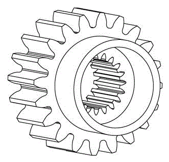
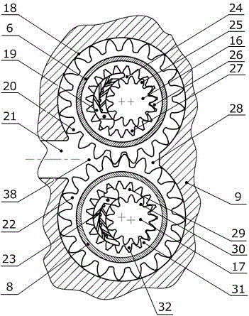
[0039] figure 1 It is a schematic cross-sectional view of the overall structure of the present invention. In the figure, the pump casing of the gear pump is composed of rear pump cover 1, rear connection cover 2, pump body 9, front connection cover 12, front pump cover 14 and other components, and a sealing ring 13 is added between the two components to prevent Leakage of oil in the pump. The first double ring gear 6, the second double ring gear 8, the radial compensation device 7, the first gear shaft 16, the second gear shaft 17, the rear side plate 5, the first front side plate 11, the second Two front side plates 10, sliding bearings 3, compensation plates 4, and sealing rings 13, wherein the first double ring gear 6 and the second double ring gear 8 are embedded in the pump body 9, and the ring gear and the pump body are transi...


PUM


Abstract

The invention discloses an internally-engaged gear pump applicable to high pressure and large flow. The internally-engaged gear pump is composed of a pump shell, a first double-tooth ring, a second double-tooth ring, a first gear shaft, a second gear shaft, a radial compensation device, a sliding bearing, a side plate and the like, wherein the first double-tooth ring and the second double-tooth ring are symmetrically arranged in the pump body, and outer teeth of the first double-tooth ring and the second double-tooth ring are engaged to form a first gear pair; the first gear shaft and the first double-tooth ring are engaged to form a second gear pair; and the second gear shaft and the second double-tooth ring are engaged to form a third gear pair. A single input shaft is used for driving the gear pairs to rotate by grades and the distribution of moment on the shaft is reasonable; and the radial unbalance force on each grade of gear pair is small and the anti-pressure ability of the pump under a high pressure working condition is improved. Oil in the pump is pressurized by the plurality of grades of gear pairs so that the output pressure and the flow of the oil are effectively improved; and meanwhile, the two paths of oil on the outlet of the pump are overlapped so that the flow and the pressure pulse of the pump are remarkably reduced and the requirements of a high-precision hydraulic system can be met.

Description

technical field [0001] The invention relates to a gear pump, in particular to an internal meshing gear pump suitable for high-pressure and high-flow working conditions. Background technique [0002] High-pressure hydraulic systems are widely used in many equipment such as casting machines, injection molding machines and forging machines. At present, with the development of high-end equipment such as military equipment and offshore drilling platforms, further high-pressure hydraulic systems have become an inevitable trend. Ultra-high pressure and large flow hydraulic systems have broad prospects, and the biggest challenge lies in the development of high-quality hydraulic pumps. [0003] Internal gear pumps are widely used in various types of construction machinery due to their outstanding features such as low noise, small oil trapping, compact structure and strong self-priming ability. However, under high pressure, the unbalanced radial force on the shaft increases rapidly, ...

Claims


Application Information

Patent Timeline
Patent Type & Authority Applications(China)
IPC IPC(8): F04C2/10F04C15/00
CPCF04C2/08F04C2/084
Inventor 杜恒王健吴强斌陈晖陈洁
Owner FUZHOU UNIV
Why Eureka
Try Eureka