
Co-wound high-voltage and low-voltage coil of transformer and winding method of co-wound high-voltage and low-voltage coil

A low-voltage coil and winding method technology, which is applied in the field of transformers, can solve the problems of high and low voltage coils with complicated procedures and low precision, and achieve the effects of improving heat dissipation, improving product quality, and shortening the production cycle

Active Publication Date: 2012-07-11
NEWONDER SPECIAL ELECTRIC
View PDF7 Cites 9 Cited by
  • Summary
  • Abstract
  • Description
  • Claims
  • Application Information

AI Technical Summary

Problems solved by technology

[0003] The purpose of the present invention is to solve the problems of complex winding process of high and low voltage coils of existing transformers and low precision after high and low voltage coils are assembled.

Method used


Image

  • Co-wound high-voltage and low-voltage coil of transformer and winding method of co-wound high-voltage and low-voltage coil
  • Co-wound high-voltage and low-voltage coil of transformer and winding method of co-wound high-voltage and low-voltage coil
  • Co-wound high-voltage and low-voltage coil of transformer and winding method of co-wound high-voltage and low-voltage coil

Examples


Embodiment Construction

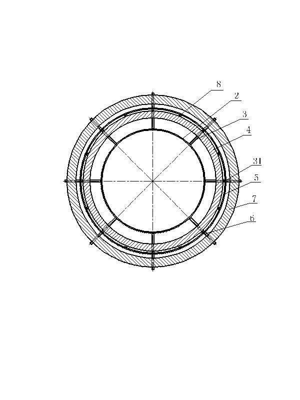
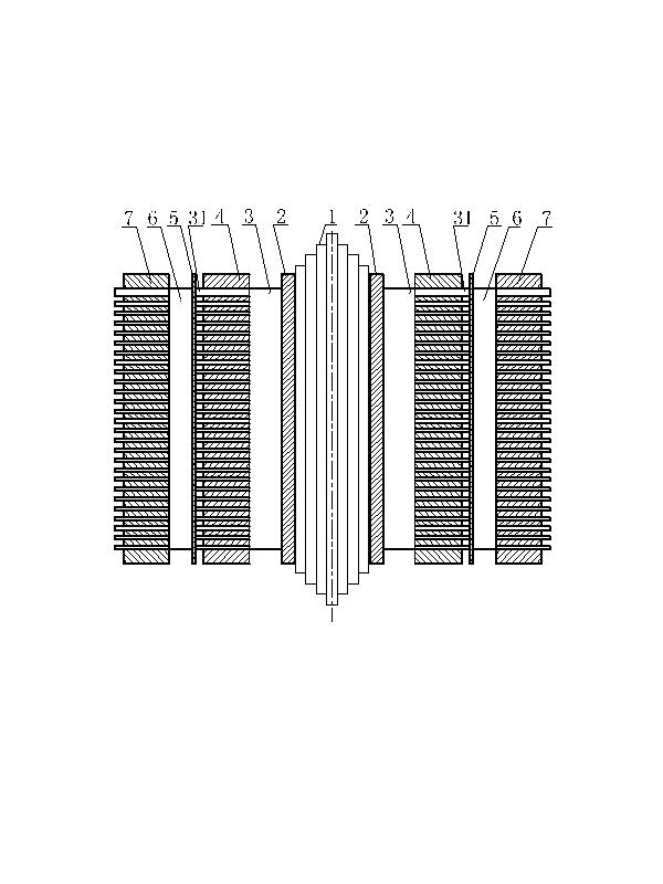
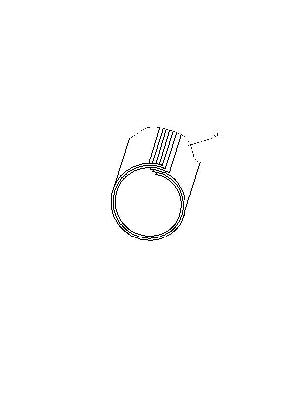
[0026] see figure 1 , figure 2 and image 3 , the high-voltage and low-voltage combined winding coil of the transformer of the present invention includes an iron core 1, a high-voltage insulating cylinder 2 arranged outside the iron core 1, and the outer surface of the high-voltage insulating cylinder 2 is provided with 8 evenly arranged high-voltage coil stays 3 , in this embodiment, the stay 3 is a comb-shaped stay, and a high-voltage coil 4 is wound outside the high-voltage coil stay 3, and the high-voltage coil stay 3 has a certain height protruding from the high-voltage coil 4 The protruding end 31, in the present embodiment, its height is selected as 5mm; a low-voltage soft paper tube 5 is arranged outside the protruding end 31 of the high-voltage coil stay, see image 3 , the low-pressure soft paper tube 5 is formed by stacking several sheets of insulating paper whose ends are staggered by a certain distance (preferably 10-15 mm) and rolled into a tube. In order to ...


PUM


Abstract

The invention discloses a co-wound high-voltage and low-voltage coil. The co-wound high-voltage and low-voltage coil comprises an iron core and a high-voltage insulating barrel, wherein the high-voltage insulating barrel is arranged at the outer part of the iron core, a high-voltage coil supporting bar is arranged on an outer surface of the high-voltage insulating barrel, and a high-voltage coil is wound at the outer part of the high-voltage coil supporting bar. The co-wound high-voltage and low-voltage coil is characterized in that the high-voltage coil supporting bar is provided with a protruding end relative to the high-voltage coil, a low-voltage soft paper barrel is arranged at the outer part of the protruding end of the high-voltage coil supporting bar, a low-voltage coil supporting bar is arranged at the outer circumference of the low-voltage soft paper barrel, and a low-voltage coil is wound at the outer part of the low-voltage coil supporting bar. According to the invention, the problems of complex winding process and much tooling equipment of the high-voltage and low-voltage coil in the prior art are solved. The co-wound high-voltage and low-voltage coil has the advantages of simple structure, simple winding process, high production efficiency and low cost.

Description

technical field [0001] The invention discloses a high-voltage and low-voltage co-winding coil of a transformer and a winding method thereof, belonging to the technical field of transformers. Background technique [0002] The current winding method of the high and low coils of the transformer is generally to arrange the stays on the outer sides of the high and low voltage insulating cylinders respectively, and then wind the high voltage coil and the low voltage coil respectively. After winding, the high-voltage coil and the low-voltage coil are set together. The disadvantages of this winding method are as follows: Each coil needs to be installed and disassembled twice, which invisibly increases the cost of man-hours; high and low voltage are wound separately, and the coils need to be packaged together when they are shaped and pressed, and the accuracy of the package is relatively high. High, if the concentricity of the coils is not well supported and the phenomenon of non-co...

Claims


Application Information

Patent Timeline
IPC IPC(8): H01F27/28H01F27/30H01F41/06
Inventor 谭勇
Owner NEWONDER SPECIAL ELECTRIC
Learn More