Eureka AIR delivers breakthrough ideas for toughest innovation challenges, trusted by R&D personnel around the world.

Middle/low-temperature geothermic efficient thermoelectric coupling combined supply system based on organic Rankine cycle (ORC)

A Rankine cycle, thermoelectric coupling technology, applied in geothermal energy systems, geothermal energy power generation, heat pumps, etc., can solve the problems affecting the service life of equipment, low geothermal utilization efficiency, and high ambient temperature, reducing water consumption and reducing power consumption. The effect of supply and demand contradiction and stable operating conditions

Inactive Publication Date: 2012-07-11
TIANJIN UNIV
View PDF4 Cites 42 Cited by
  • Summary
  • Abstract
  • Description
  • Claims
  • Application Information

AI Technical Summary

Problems solved by technology

In other seasons, the situation is just the opposite, especially in summer, due to the high ambient temperature, low power generation efficiency, and smaller heat demand than winter, so the recharge temperature is high and the geothermal utilization efficiency is low
In addition, the ambient temperature changes day and night and seasonally, so that the operating state of the system changes instantaneously, which seriously affects the service life of the equipment

Method used


Image

  • Middle/low-temperature geothermic efficient thermoelectric coupling combined supply system based on organic Rankine cycle (ORC)
  • Middle/low-temperature geothermic efficient thermoelectric coupling combined supply system based on organic Rankine cycle (ORC)
  • Middle/low-temperature geothermic efficient thermoelectric coupling combined supply system based on organic Rankine cycle (ORC)

Examples


Embodiment Construction

[0016] The principle of the present invention and the component connection structure will be further described below in conjunction with the drawings and embodiments. It should be noted that this embodiment is descriptive rather than restrictive, and the protection scope of the present invention is not limited by this embodiment.

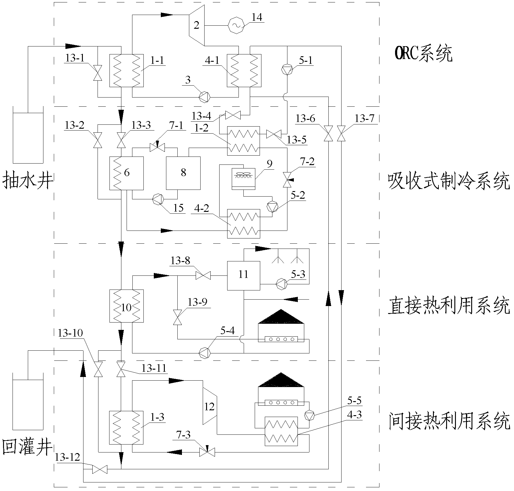
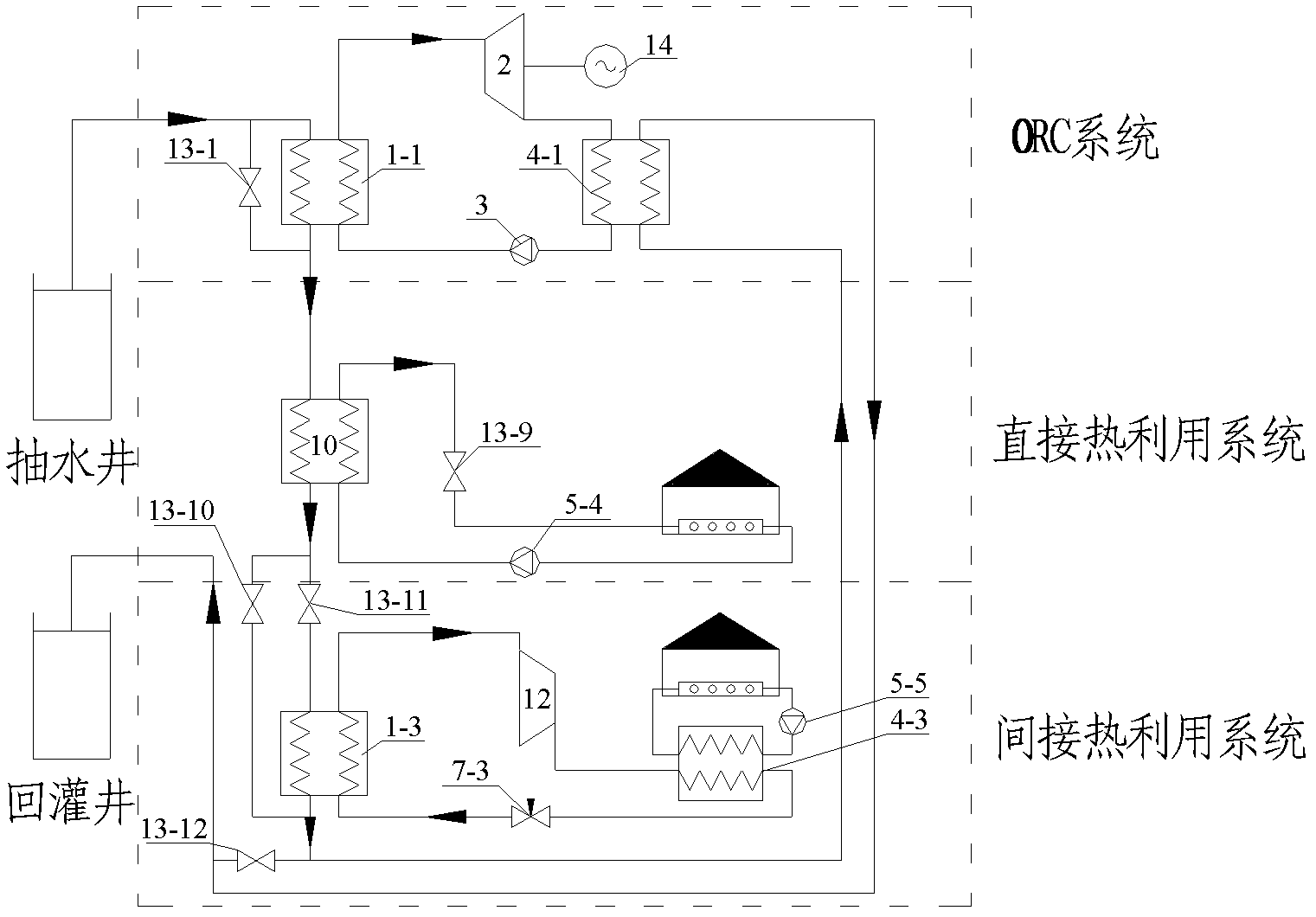
[0017] Medium-low temperature geothermal high-efficiency thermoelectric cogeneration system based on organic Rankine cycle (such as figure 1 ), which is composed of the working medium side of the first evaporator 1-1, the steam turbine 2, the first condenser 4-1 and the working medium pump 3 connected in sequence through pipelines, and includes a generator 14 and a first water pump 5-1 Organic Rankine cycle power generation system. It is connected in sequence by the second evaporator 1-2, the second throttle valve 7-2, the second condenser 4-2, the generator 6 and the absorber 8, and includes the first throttle valve 7-1 and the solution pump 15. ...


PUM


Abstract

The invention relates to a middle / low-temperature geothermic efficient thermoelectric coupling combined supply system based on an organic Rankine cycle (ORC), which has the main technical structure as follows: an ORC system, an absorption refrigeration system, a direct heat utilization system and an indirect heat utilization system are connected in series through a geothermic water supply pipeline. Specifically, after geothermic water supply is orderly connected to a first evaporator, a generator, a plate type heat exchanger and a third evaporator, the geothermic water supply is connected to inlets of a first condenser and a second evaporator in parallel, and the water discharged from the first condenser is introduced to a geothermic recharge well. Water discharged from a low-temperature side of the plate type heat exchanger is divided into two paths, one path is connected to a hot water storage box; and the other path is connected to a tail end device of the direct heat utilization system and then returns to a low-temperature water inlet of the plate type heat exchanger by means of a water pump. A valve and a water pump are orderly arranged between water sides of the first condenser and the second evaporator in series. According to the invention, geothermic tail water is adopted as a heat source so as to conform to energy saving and emission reduction requirements and be beneficial to environmental protection; and besides the utilization efficiency of the geothermic resources is improved, the system has a remarkable effect on reducing the emission of contaminants.

Description

technical field [0001] The invention belongs to the utilization of renewable energy, and in particular relates to a thermal energy comprehensive utilization system coupled with organic Rankine cycle, absorption refrigeration and utilization of geothermal tail water. Background technique [0002] The organic Rankine cycle is a Rankine power cycle that uses organic matter instead of water as the working medium. It uses low-grade heat energy to heat the organic working medium to generate steam, and then drives the steam turbine generator set to generate electricity. The temperature of the heat source in the Organic Rankine Cycle (ORC) system is usually above 90°C, and the temperature of the geothermal water after power generation is generally higher than 75°C. Rational use of geothermal water can improve the efficiency of power generation and the technical economy of the system. In winter, the outdoor temperature is low, the condensation temperature of the power generation sys...

Claims


Application Information

Patent Timeline
IPC IPC(8): F03G4/00F01K25/10F25B15/00F25B30/06
CPCY02B30/62Y02E10/10Y02A30/27Y02P80/15
Inventor 朱家玲李太禄张伟
Owner TIANJIN UNIV
Why Eureka
Eureka Blog
Learn More