
Tunnel kiln

A technology of tunnel kiln and gas channel, which is applied in the field of tunnel kiln, can solve the problems of increasing time-consuming temperature rise in sintering section, long time-consuming temperature rising in sintering section, limited drying heating capacity, etc., and achieve the effect of high temperature, short sintering time-consuming, and convenient complete combustion

Inactive Publication Date: 2012-07-04
NORTHWESTERN POLYTECHNICAL UNIV
View PDF5 Cites 4 Cited by
  • Summary
  • Abstract
  • Description
  • Claims
  • Application Information

AI Technical Summary

Problems solved by technology

However, through analysis and field tests, it is found that the tunnel kiln of the prior art still has the potential to further reduce energy consumption. There are three reasons: first, the waste heat recovery of flue gas is only used for raw meal drying in the raw meal drying kiln, However, the drying process of the raw meal drying kiln is not continuous and the amount of drying heating required is limited, and the recovered flue gas waste heat is often discharged into the high-altitude environment through the outdoor exhaust chimney; secondly, during the gas combustion process of the tunnel kiln , because the air used for combustion in the sintering section comes from the cold air in the environment, which makes the temperature of the flue gas generated by the gas combustion in the sintering section not very high, resulting in a long time-consuming temperature rise in the sintering section, high energy consumption for sintering, and high sintering requirements. The difficulty of controlling the technical quality of continuous high temperature increases; third, the combustion chamber of the tunnel kiln is the sintering section in the tunnel kiln. During the sintering process of the sintering section, more non-combustion-supporting flue gas is gradually accumulated. The gas used is fully combusted, so the amount of combustion-supporting air has to be increased, which leads to a larger air-fuel ratio, which also causes the temperature rise in the sintering section to increase in time, the energy consumption of sintering increases, and the continuous sintering required It is more difficult to control the technical quality of high temperature

Method used


Image

  • Tunnel kiln
  • Tunnel kiln
  • Tunnel kiln

Examples


Embodiment Construction

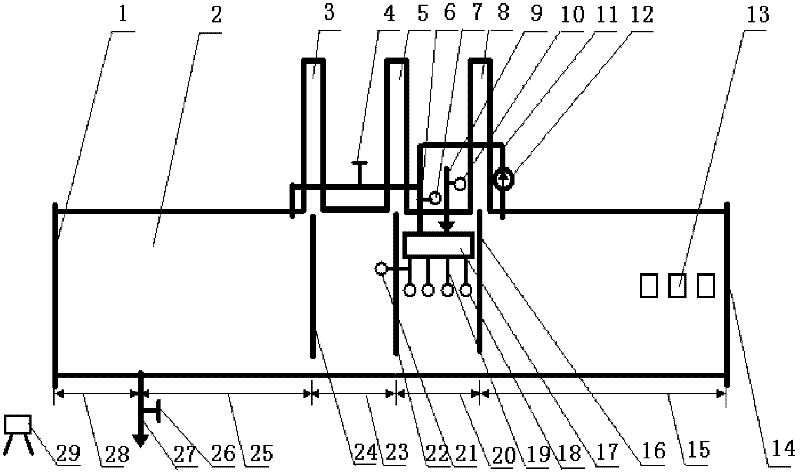
[0019] This embodiment is a straight tunnel kiln, the inner wall of the tunnel is laid with refractory insulation materials, and the bottom has guide rails for refractory brick transport vehicles, including kiln head door 1, front hanging door opening 3, hot gas valve 4, middle hanging door opening 5, heating Air pipe tee 6, hot gas flow meter 7, rear hanging door hole 8, gas flow meter 10, hot gas channel 11, hot gas blower 12, suction port 13, kiln tail door 14, rear hanging door 16, combustion chamber 17, flue gas nozzle 18. Flue gas passage 19, flue gas meter 21, middle hanging door 22, heat recovery section 23, front hanging door 24, waste heat valve 26, waste heat gas passage 27 and monitor 29, of which:

[0020] Along the depth direction of tunnel kiln 2, there are kiln head door 1, kiln entry section 28, preheating section 25, reheating section 23, sintering section 20, cooling section 15 and kiln tail door 14, in which the tunnel kiln preheating The section is divided...


PUM


Abstract

The invention relates to a tunnel kiln. A kiln front door and a kiln back door are arranged to decrease external heat dissipation of two end openings of the tunnel kiln; a back heating section, a front hanging door, a middle hanging door and a rear hanging door are arranged to decrease dissipation of heat of a sintering section into the tunnel kiln or other areas and reduce energy consumption of the tunnel kiln, wherein the front hanging door, the middle hanging door and the rear hanging door are refractory, heat-insulating and controllable and are arranged at the initial end of the back heating section, at the initial end of the sintering section and at the tail end of the sintering section; a waste hot air recovery channel is arranged to recover waste hot air in a cooling section; and acombustion chamber outside the tunnel kiln is arranged and the waste hot air in the cooling section is recycled, so that the sintering section of the tunnel kiln obtains air-fuel ratio of efficient combustion, and fuels are more conveniently controlled to sufficiently combust. The sintering section of the tunnel kiln is less in energy consumption and high in temperature, and the tunnel kiln has the advantages of high waste heat utilization level, short sintering time and low energy consumption.

Description

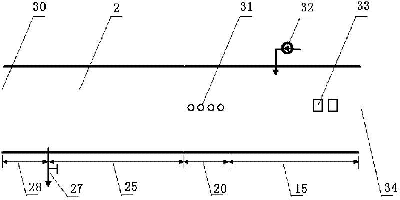
technical field [0001] The invention relates to the field of refractory material production, in particular to a tunnel kiln. Background technique [0002] Tunnel kiln is the main equipment for the production of refractory products, and it is also the main energy-consuming equipment of the refractory factory. Compared with the traditional downdraft kiln, the tunnel kiln has the advantages of high production efficiency and low fuel consumption, and is currently widely used in the production of sintered refractory materials. [0003] The current refractory brick tunnel kiln, see attached figure 2 The side view of the tunnel kiln, the main body is a straight-through tunnel, and the inner wall of the tunnel is covered with refractory insulation materials. Along the depth direction of the tunnel, it is divided into kiln head, kiln entry section, preheating section, sintering section, cooling section and The end of the kiln. The kiln head is the entrance for transporting raw mat...

Claims


Application Information

Patent Timeline
Patent Type & Authority Applications(China)
IPC IPC(8): F27B9/02F27B9/36F27B9/40F27D17/00
Inventor 李世武冷国伟肖力新
Owner NORTHWESTERN POLYTECHNICAL UNIV
Learn More