UV Optical Delivery Systems for Wafer Dicing Equipment

A technology of cutting equipment and transmission system, applied in welding equipment, laser welding equipment, metal processing equipment, etc., can solve the problems of LED chip light decay and life reduction, increase the difficulty of process exploration, and it is difficult to determine the cutting effect, etc., to achieve Effects of reducing irradiation intensity, improving convenience, and increasing lifespan

Active Publication Date: 2016-02-17
FUJIAN INST OF RES ON THE STRUCTURE OF MATTER CHINESE ACAD OF SCI
View PDF4 Cites 0 Cited by
  • Summary
  • Abstract
  • Description
  • Claims
  • Application Information

AI Technical Summary

Problems solved by technology

When this diffracted light is cut, it will cause burning on both sides of the cutting line, and this burning is the main culprit of LED chip light decay and life reduction
[0005] In addition, the working conditions of the ultraviolet laser used in the current LED ultraviolet cutting equipment are relatively fixed. Generally, the laser output power can only be adjusted in a relatively small current range. However, when the laser operating current changes, not only the laser output power changes, but also the laser pulse width. Therefore, when exploring the wafer process, it is difficult to determine whether the change in the cutting effect is due to the change in laser power or the change in pulse width, or the effect of both.
Therefore, this method increases the difficulty of process exploration

Method used


Image

  • UV Optical Delivery Systems for Wafer Dicing Equipment
  • UV Optical Delivery Systems for Wafer Dicing Equipment
  • UV Optical Delivery Systems for Wafer Dicing Equipment

Examples


Embodiment Construction

[0016] Embodiments of the present invention will be further described below in conjunction with the accompanying drawings.

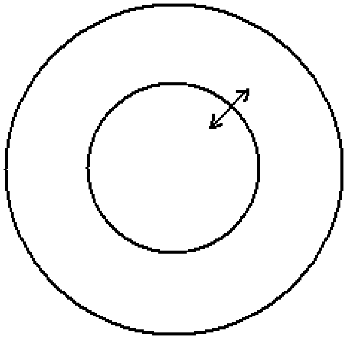
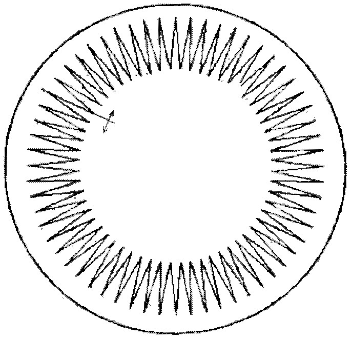
[0017] Figure 5 It is a schematic diagram of the structure of the ultraviolet laser transmission optical path. The laser output from the ultraviolet laser 1 passes through the λ / 2 wave plate 2 to rotate the polarization direction, and then passes through the polarizer 3 to analyze the radial polarization. A part of the laser light is reflected by the polarizer and then injected into the receiving bucket 4 to be received. The other part of the laser light is transmitted through the polarizer 3; the λ / 2 wave plate 2, the polarizer 3 and the receiving bucket 4 form a laser power adjustment module, which can conveniently adjust the laser power without changing the laser pulse width. The laser light passing through the polarizer 3 passes through the serrated diaphragm 5 and reflects a part of the laser light on the 45-degree beam splitter 6 and shoots it to ...


PUM

PropertyMeasurementUnit
widthaaaaaaaaaa
depthaaaaaaaaaa

Abstract

The invention discloses an ultraviolet optical transmission system for wafer cutting equipment, which relates to an optical transmission design method applied to LED wafer cutting ultraviolet laser precision machining equipment, and belongs to the field of laser precision machining. By proposing a new ultraviolet laser transmission design scheme, the radiation intensity of diffraction beams of an ultraviolet laser to an LED chip is reduced, the service life of the LED chip is prolonged, the power of the laser is conveniently adjusted and monitored in real time, and the ultraviolet optical transmission system has important practical significance for integrally improving the machinability of wafer cutting equipment.

Description

technical field [0001] The invention discloses a design of an ultraviolet optical transmission system for wafer cutting equipment, relates to an optical transmission design method applied to LED wafer cutting ultraviolet laser precision processing equipment, and belongs to the field of laser precision processing. Background technique [0002] As we all know, traditional LED wafer cutting adopts grinding wheel, diamond and other methods for mechanical cutting, but there are shortcomings such as wide cutting line and slow processing speed. The cutting line width reaches more than 30 microns, and the cutting speed of 2-inch wafer cutting can only reach 1 ~2 tablets / hour. With the development of the semiconductor industry, a large number of hard substrates such as sapphire are used in LED wafers. At the same time, the grain size on LED wafers is getting smaller and smaller. Traditional mechanical cutting methods are increasingly unable to meet the needs of industrial development...

Claims


Application Information

Patent Timeline
Patent Type & Authority Patents(China)
IPC IPC(8): B23K26/064B23K26/38B23K26/06
Inventor 黄见洪翁文刘华刚葛燕阮开明邓晶郑晖李锦辉史斐戴殊韬吴鸿春林文雄
Owner FUJIAN INST OF RES ON THE STRUCTURE OF MATTER CHINESE ACAD OF SCI
Why Eureka
Try Eureka