
High gain bidirectional end-fire antenna array applied to mine and tunnel

An end-fire antenna and high-gain technology, applied in the field of high-gain bidirectional end-fire antenna arrays, can solve problems such as unsuitability, increase communication distance, and reduce communication quality, so as to reduce design and manufacturing costs, reduce power loss, Achieve the effect of impedance matching

Active Publication Date: 2012-06-27
TSINGHUA UNIV
View PDF5 Cites 27 Cited by
  • Summary
  • Abstract
  • Description
  • Claims
  • Application Information

AI Technical Summary

Problems solved by technology

However, leaky cables have many disadvantages: firstly, the laying cost of leaky cables is relatively high, and maintenance is also relatively difficult, which is not suitable for scenarios where the mine operation site changes frequently and the flow of workers is scattered; secondly, the transmission attenuation of leaky cables is greater than The inherent attenuation of the coaxial cable itself, when applied to long-distance communication, the attenuation increases significantly with the increase of the communication distance, so it is necessary to cut off and increase the repeater to increase the communication distance, which increases the complexity of the system and cost overhead, when the system is too large, too many repeaters will increase the background noise sharply, which will reduce the communication quality; moreover, the transmission and reception of the leaky cable communication system need to be switched by the base station, and the failure of the base station will make the entire communication system down
In order to ensure the safety of the workers in the mine, the mine roadway requires a wind speed of 2-6m / s. However, the above-mentioned antennas are all planar structures (circular, oval, or square, etc.), and the windward area is relatively large. When arranged in the mine Inside, the ventilation of the roadway is greatly affected, and dust and the like are easy to accumulate on the surface of the antenna, which gradually reduces the radiation performance of the antenna

Method used

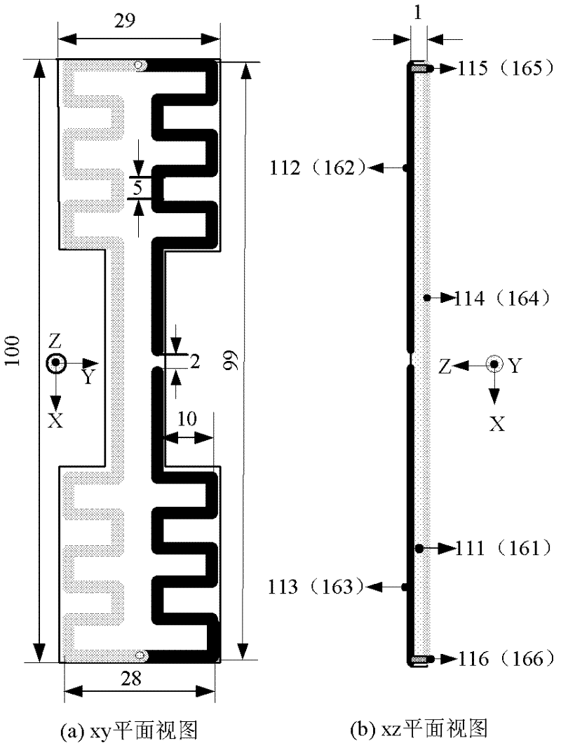

Image

  • High gain bidirectional end-fire antenna array applied to mine and tunnel
  • High gain bidirectional end-fire antenna array applied to mine and tunnel
  • High gain bidirectional end-fire antenna array applied to mine and tunnel

Examples


Embodiment Construction

[0037] The present invention will be described in further detail below in conjunction with the accompanying drawings and embodiments.

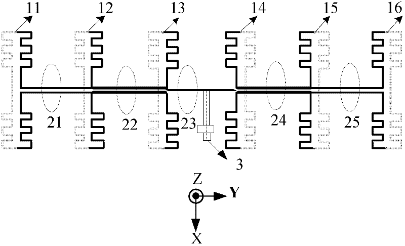
[0038] Such as figure 1 Shown, the high-gain two-way endfire antenna array of the present invention comprises:

[0039] Antenna unit 1, a total of six, respectively the first antenna unit 11, the second antenna unit 12, the third antenna unit 13, the fourth antenna unit 14, the fifth antenna unit 15, the sixth antenna unit 16;

[0040] There are five groups of series feeding transmission lines 2, namely the first transmission line 21, the second transmission line 22, the third transmission line 23, the fourth transmission line 24, and the fifth transmission line 25, wherein the first transmission line 21, the second transmission line 22, the Both the four transmission lines 24 and the fifth transmission line 25 are composed of horizontal and parallel first two-wire transmission lines and second two-wire transmission lines, and the third trans...

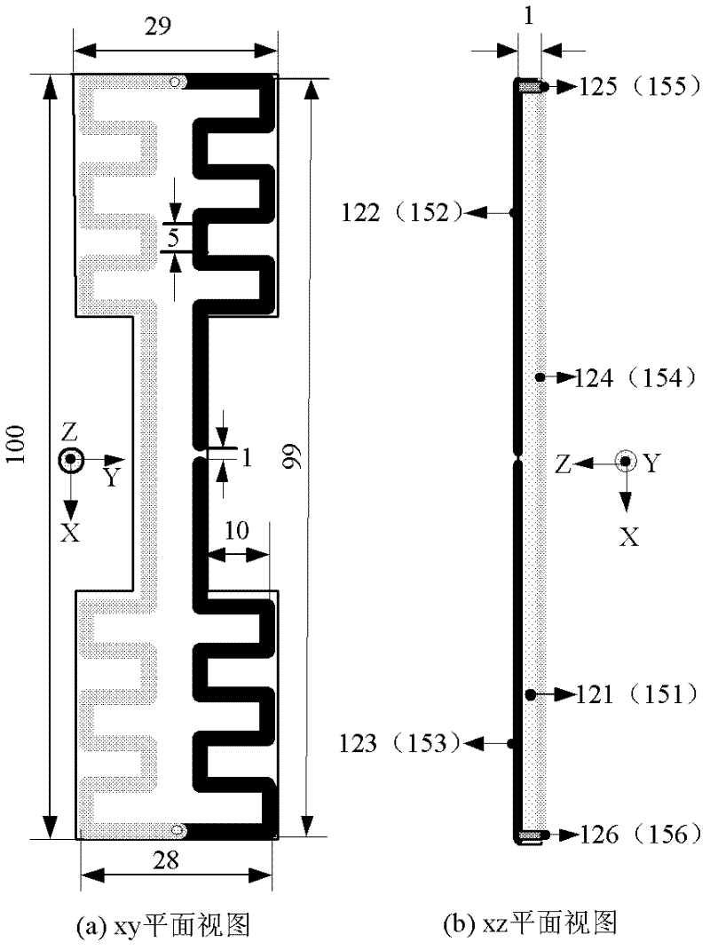

PUM


Abstract

The invention provides a high gain bidirectional end-fire antenna array applied to a mine and a tunnel, belonging to the antenna design field in wireless communication. A folded dipole with a bending line as a dipole arm is employed as an antenna unit which has a compact structure. An antenna unit medium plate employs an I shape structure, introduced discontinuity is reduced when a feed transmission line steps across the antenna unit, and reflection is reduced. A series connection feed form with combination of horizontal parallel double-line and vertical parallel double-line structures is used, reverse excitation and impedance match of adjacent units are realized, and high gain bidirectional end-fire radiation is obtained. The antenna array is suitable for realization of wireless communication in a typical non-free space transmission channel with limited space such as the mine and the tunnel, and the antenna array has the advantages of the compact antenna unit, a small windward area, low cost and a high gain.

Description

technical field [0001] The invention belongs to the antenna design field of wireless communication technology, and relates to a high-gain bidirectional end-fire antenna array, in particular to a high-gain bidirectional end-fire antenna array applied to mines and roadways. Background technique [0002] Mine is a typical non-free space propagation channel with limited space. When electromagnetic waves propagate in it, frequent reflection, diffraction, and scattering are caused by the four walls of the roadway and irregularly distributed objects in the mine, resulting in significant multipath effects. , At the same time, the electromagnetic wave is absorbed and reflected by the rocks and ores in the mine, so the attenuation is very fast, and the transmission distance is greatly shortened. [0003] Since wired channels are more stable than wireless channels, mature ground wired communication solutions can be relatively easily transferred to mine communications. Therefore, early ...

Claims


Application Information

Patent Timeline
IPC IPC(8): H01Q1/38H01Q21/00
Inventor 张志军刘龙生冯正和
Owner TSINGHUA UNIV
Learn More