Eureka AIR delivers breakthrough ideas for toughest innovation challenges, trusted by R&D personnel around the world.

Automatic optical inspection method and automatic optical inspection equipment

An automatic optical inspection, optical automatic inspection technology, applied in the direction of optical testing flaws/defects, optics, nonlinear optics, etc., can solve the problems of high price, high cost, large amount of information, etc., to achieve repeatability and speed increase, reduce requirements, the effect of reducing input costs

Active Publication Date: 2015-02-11
TCL CHINA STAR OPTOELECTRONICS TECH CO LTD
View PDF4 Cites 0 Cited by
  • Summary
  • Abstract
  • Description
  • Claims
  • Application Information

AI Technical Summary

Problems solved by technology

However, the system needs to use expensive AOI equipment, which has a high cost; at the same time, due to the use of image contrast technology, the digital-to-analog conversion of the image generates a larger amount of information, which has a greater negative impact on graphics processing

Method used


Image

  • Automatic optical inspection method and automatic optical inspection equipment
  • Automatic optical inspection method and automatic optical inspection equipment
  • Automatic optical inspection method and automatic optical inspection equipment

Examples


Embodiment Construction

[0025] The present invention will be further described below in conjunction with the accompanying drawings and preferred embodiments.

[0026] An optical automatic detection device of the present invention includes a photography device for acquiring grayscale information of an image of an object to be inspected, and a computing module for receiving the grayscale information and generating a standard image for automatic optical detection. The automatic optical detection method of the optical automatic detection equipment can be applied to the detection of liquid crystal substrates, surface mount technology (Surface Mounted Technology, SMT) and other products. In this embodiment, the liquid crystal substrates applied to them are taken as examples for illustration.

[0027] The manufacturing process of the TFT-LCD includes an array process (Array) and a color filter process (Color Filter, CF, color filter plate). The graphics in the array process and the color filter process are c...


PUM


Abstract

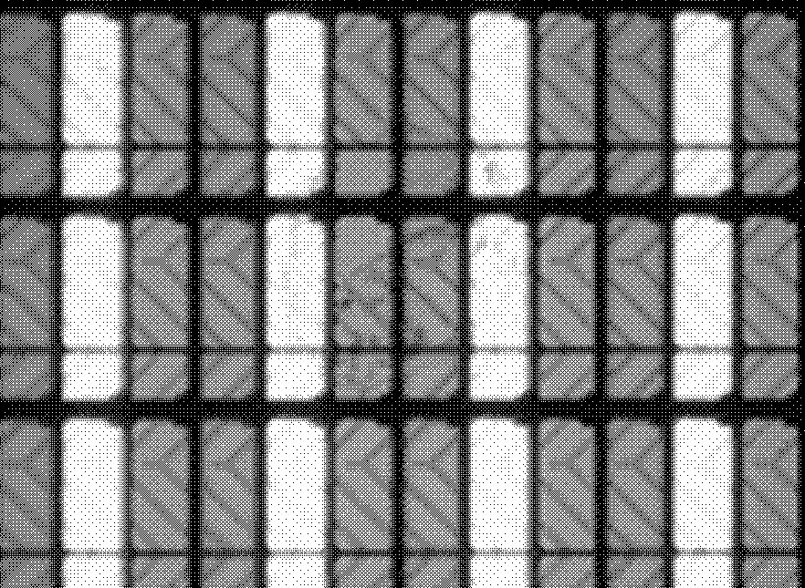
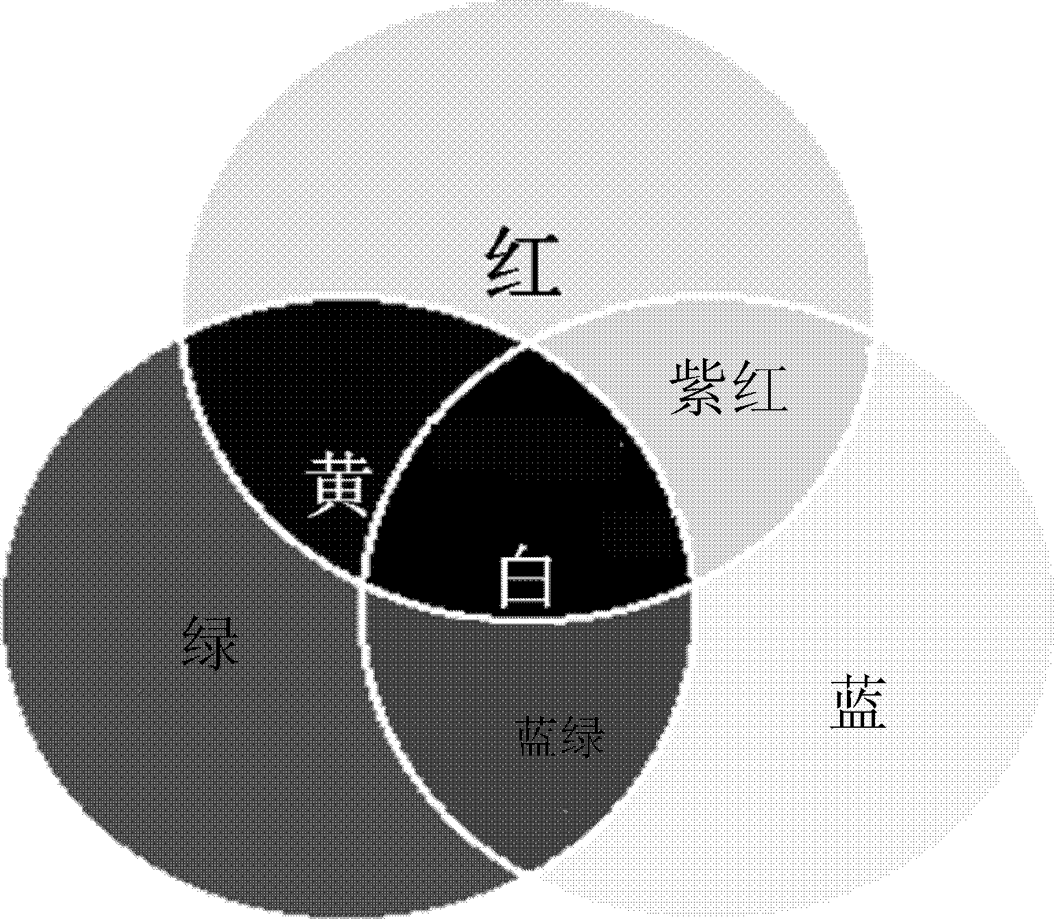
The present invention relates to an automatic optical detection method and automatic optical detection device, the automatic optical detection method comprising the following steps: color light projection step, uniformly projecting the three primary colors of light on an object to be detected, and forming an image with different colors; obtaining the gray scale information corresponding to different areas of the image, and then generating a standard image for automatic optical inspection; and comparing the standard image for automatic optical inspection with a pre-stored reference image. The present invention only needs to process the grey scale information of the image, thus reducing the data volume and the processing difficulty of an image processing unit and a statistical analysis unit, and improving data acquisition reliability, precision, repeatability and speed. The present invention reduces the requirements on the detection device, thus facilitating the reduction of detection device input cost.

Description

technical field [0001] The invention relates to an automatic optical detection method, in particular to an automatic optical detection method and optical automatic detection equipment applied to a thin film transistor liquid crystal display (Thin Film Transistor Liquid Crystal Display, TFT-LCD). Background technique [0002] At present, the Automatic Optical Inspection (AOI) system in the TFT-LCD industry uses a graphic comparison algorithm for detection, that is, through high-definition camera technology, image analog-to-digital conversion technology, data image processing and analysis technology, and computer automation. Control technology and test result statistics analyze the image. However, this system needs to use expensive AOI equipment, which has a high cost; at the same time, due to the use of image contrast technology, the digital-to-analog conversion of the image generates a larger amount of information, which has a greater negative impact on image processing. C...

Claims


Application Information

Patent Timeline
Patent Type & Authority Patents(China)
IPC IPC(8): G02F1/13G01N21/956
CPCG01N21/88G01N21/25G02F1/1309G01N21/293G02F1/13
Inventor 寇浩
Owner TCL CHINA STAR OPTOELECTRONICS TECH CO LTD
Why Eureka
Eureka Blog
Learn More