Method for producing disilane by reaction of magnesium silicide and ammonium chloride
A technology of disilane and ammonium chloride, applied in the direction of silicon hydride and the like, can solve the problems of high production cost, many impurity gases, long process, etc., and achieve the effects of low production cost, high economic benefit and low investment.
- Summary
- Abstract
- Description
- Claims
- Application Information
AI Technical Summary
Problems solved by technology
Method used
Image
Examples
Embodiment 1
[0023] A method for producing disilane by chemical reaction of magnesium silicide and ammonium chloride in a liquid ammonia medium, characterized in that the silicide is produced by synthesizing silane at 800°C,
[0024] 2Mg 2 Si + 8NH 4 Cl Si 2 h 6 + 4MgCl 2 + 8NH 3 + H 2
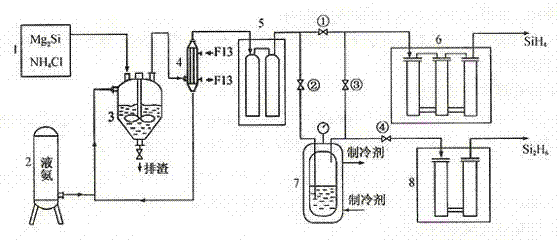
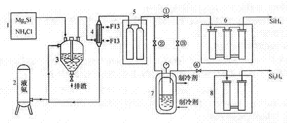
[0025] Close 1#, 4# valves, open 2# and 3# valves; the mixed gas flow from the crude silane purification unit (the main component is H 2 、SiH 4 、Si 2 h 6 ...), flowing through the -110°C cold trap, disilane becomes liquid and condenses in the disilane liquefaction bottle, and silane and hydrogen continue to enter the next purification process along the pipeline; when disilane is in the liquefaction bottle After the income reaches a certain amount, close the 2# and 3# valves, open the 1# and 4# valves; ① let the silane production continue; Silane products.
Embodiment 2
[0027] A method for producing disilane by chemical reaction of magnesium silicide and ammonium chloride in a liquid ammonia medium, characterized in that the silicide is produced by synthesizing silane at 600°C,
[0028] 2Mg 2 Si + 8NH 4 Cl Si 2 h 6 + 4MgCl 2 + 8NH 3 + H 2
[0029] Close 1#, 4# valves, open 2# and 3# valves; the mixed gas flow from the crude silane purification unit (the main component is H 2 、SiH 4 、Si 2 h 6 ...), flowing through the -110°C cold trap, disilane becomes liquid and condenses in the disilane liquefaction bottle, and silane and hydrogen continue to enter the next purification process along the pipeline; when disilane is in the liquefaction bottle After the income reaches a certain amount, close the 2# and 3# valves, open the 1# and 4# valves; ① let the silane production continue; Silane products.
Embodiment 3
[0031] A method for producing disilane by chemical reaction of magnesium silicide and ammonium chloride in a liquid ammonia medium, characterized in that the silicide is produced by synthesizing silane at 900°C,
[0032] 2Mg 2 Si + 8NH 4 Cl Si 2 h 6 + 4MgCl 2 + 8NH 3 + H 2
[0033] Close 1#, 4# valves, open 2# and 3# valves; the mixed gas flow from the crude silane purification unit (the main component is H 2 、SiH4 、Si 2 h 6 ...), flowing through the -110°C cold trap, disilane becomes liquid and condenses in the disilane liquefaction bottle, and silane and hydrogen continue to enter the next purification process along the pipeline; when disilane is in the liquefaction bottle After the income reaches a certain amount, close the 2# and 3# valves, open the 1# and 4# valves; ① let the silane production continue; Silane products.
PUM
 Abstract
Description
Claims
Application Information
 - R&D Engineer
- R&D Manager
- IP Professional
- Industry Leading Data Capabilities
- Powerful AI technology
- Patent DNA Extraction
Browse by: Latest US Patents, China's latest patents, Technical Efficacy Thesaurus, Application Domain, Technology Topic, Popular Technical Reports.
© 2024 PatSnap. All rights reserved.Legal|Privacy policy|Modern Slavery Act Transparency Statement|Sitemap|About US| Contact US: help@patsnap.com


