Clamping device for manufacturing bearing

A clamping device and bearing processing technology, applied in metal processing equipment, manufacturing tools, honing machine tools, etc., can solve the problems of unstable inner diameter gap, shortened service life of copper sleeve, low equipment productivity, etc., to improve production efficiency and production. Quality, increase service life and reduce maintenance costs

Inactive Publication Date: 2012-06-27
SUZHOU DONGLI MACHINERY
View PDF0 Cites 0 Cited by
  • Summary
  • Abstract
  • Description
  • Claims
  • Application Information

AI Technical Summary

Problems solved by technology

But in the process of using, it is found that this device has many disadvantages
During the processing, due to the vibration of the main shaft, the gap between the outer diameter of the copper sleeve of the clamping device and the inner diameter of the processed product is unstable, and a certain eccentricity occurs, resulting in friction between the processed product and the copper sleeve during high-speed rotation. Wear and tear, resulting in dimensional deviation and high scrap rate; due to the wear of the copper sleeve during the production process, the replacement frequency of the copper sleeve is high, and the interference fit is adopted between the copper sleeve and the guide shaft. It is very inconvenient when the inner ring of the type bearing needs to replace the copper sleeve, and after replacement, the service life of the copper sleeve will be shortened or it will not be used directly, resulting in low productivity of the equipment and low product quality

Method used


Image

  • Clamping device for manufacturing bearing
  • Clamping device for manufacturing bearing
  • Clamping device for manufacturing bearing

Examples


Embodiment Construction

[0011] The present invention is described below in conjunction with accompanying drawing.

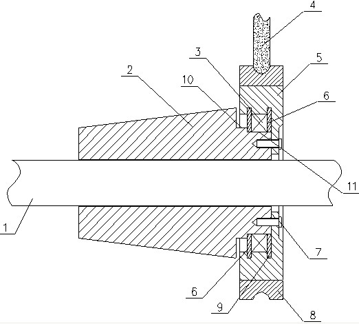
[0012] attached figure 2 It is a clamping device for bearing processing according to the present invention, which includes a guide shaft 2 and a clamping sleeve 5; the guide shaft 2 is fixed on the main shaft 1 of the machine tool; the clamping sleeve 5 is fixed on the tail of the guide shaft 2 end, and the bearing inner ring 8 to be processed is fixed on the clamping sleeve 5; the tail end of the guide shaft 2 is provided with an outer positioning shoulder 11 and an inner transitional shoulder 10; the clamping sleeve 5 is fixed on the outer positioning 11 on the shoulder; the clamping sleeve 5 is disc-shaped, and the inner bottom surface of the clamping sleeve 5 is close to the end surface of the outer positioning shoulder 11; between the inner side of the clamping sleeve 5 and the outer positioning shoulder 11 The bearing 3 is connected and fixed; the axial sides of the bearing 3 ar...


PUM


Abstract

The invention discloses a clamping device for manufacturing a bearing, which comprises a guiding shaft and a clamping sleeve. The guiding shaft is fixed on a main shaft of a machine tool, the clamping sleeve is fixed at the tail end of the guiding shaft, and bearing inner races to be manufactured are fixed on the clamping sleeve. An outside locating shaft shoulder and an inside locating shaft shoulder are arranged at the tail end of the guiding shaft, the disc-shaped clamping sleeve is fixed on the outside locating shaft shoulder, the undersurface inside the clamping sleeve is closely attached to an end face of the outside locating shaft shoulder, the inside of the clamping sleeve is connected and fixed with the outside locating shaft shoulder through the bearing, elastic clamping plates are arranged on two sides of the bearing in the axial direction, and the upper ends of the elastic clamping plates are inserted in clamping grooves arranged inside the clamping sleeve and matched with the clamping plates. The elastic clamping plates respectively abut against the undersurface inside the clamping sleeve and the end face of the inside locating shaft shoulder. A plurality of bolts are arranged at the bottom of the clamping sleeve which is fixed on the guiding shaft. The clamping device is low in cost and solves the problem of high product rejection rate and inconvenient use.

Description

technical field [0001] The invention relates to a clamping device, which belongs to the field of clamping devices for bearing processing. Background technique [0002] Bearing is an important component in contemporary mechanical equipment. Its main function is to support the mechanical rotating body to reduce the friction coefficient of mechanical load generated by the equipment during transmission. Bearings vary in size and form, and are widely used in precision instruments, low-noise motors, automobiles and other mechanical industries. According to the friction properties of moving parts, bearings can be divided into two types: rolling bearings and sliding bearings. Due to the wide application range of bearings and the relatively large market demand, the bearing processing technology has been continuously improved, and there are many kinds of clamping devices for bearing processing, but in most bearing processing processes, The structure of the clamping device used in bea...

Claims


Application Information

Patent Timeline
IPC IPC(8): B24B33/10
Inventor 叶晓峰
Owner SUZHOU DONGLI MACHINERY
Why Eureka
Try Eureka