
Extended integral flat heat pipe at condensation end

A technology of flat heat pipe and condensing end, which is applied in indirect heat exchangers, lighting and heating equipment, etc., can solve the problems of reducing the heat dissipation efficiency of radiators, achieve the effect of solving high heat flow problems, simplifying the processing process, and improving heat dissipation performance

Active Publication Date: 2012-06-20
淳华氢能源科技(湖南)有限公司
View PDF6 Cites 42 Cited by
  • Summary
  • Abstract
  • Description
  • Claims
  • Application Information

AI Technical Summary

Problems solved by technology

There is a large temperature difference between the base and the end of the traditional heat dissipation fin, and its flat heat pipe can only achieve uniform temperature at the base of the heat dissipation fin. This large temperature difference reduces the heat dissipation efficiency of the radiator

Method used


Image

  • Extended integral flat heat pipe at condensation end
  • Extended integral flat heat pipe at condensation end
  • Extended integral flat heat pipe at condensation end

Examples


Embodiment Construction

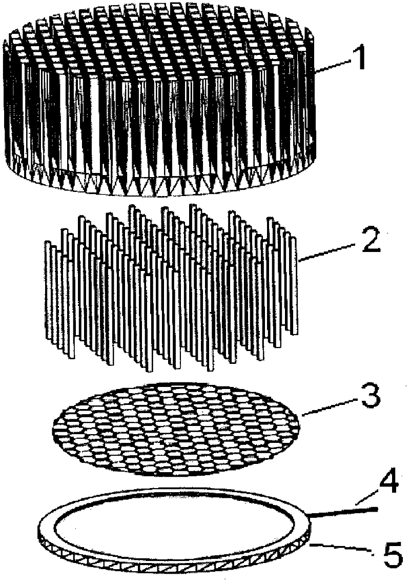
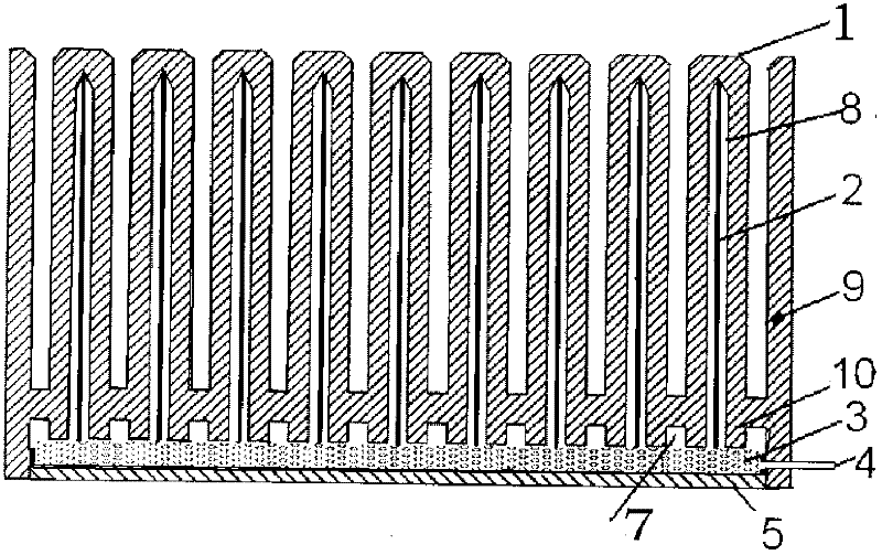
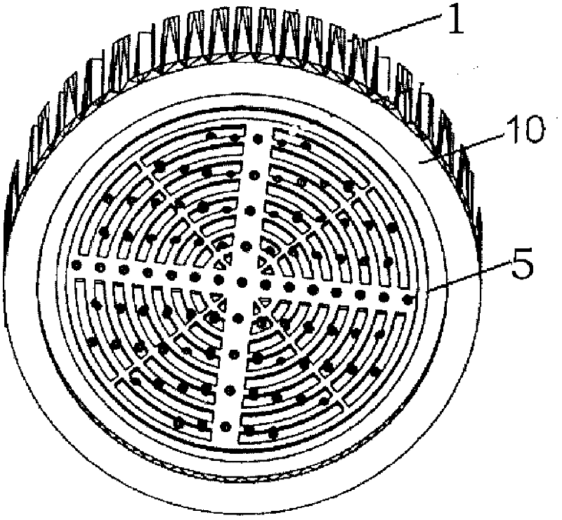
[0017] The invention provides an extended integrated flat heat pipe at the condensing end. Be described below in conjunction with accompanying drawing. figure 1 Shown is a schematic diagram of the assembly structure of the extended integrated flat heat pipe at the condensation end. figure 2 Shown is a schematic cross-sectional view of the integration of cooling fins and flat heat pipes. In the figure, the flat heat pipe includes the outer fins 9 of the heat dissipation fins 1 fixed to the bottom plate 5, that is, the bottom plate 5 of the flat heat pipe is packaged with the periphery of the bottom 10 of the heat dissipation fins. Porous metal material (porous materials such as copper foam, aluminum foam and nickel foam, etc., copper foam is the best) layer 3 is attached to the bottom plate 5 by sintering, and the gap between the middle fins of the cooling fins 1 and the middle The gaps between the fins and the outer fins 9 are equal and connected to each other at the heat d...


PUM


Abstract

The invention discloses an extended integral flat heat pipe at a condensation end, which belongs to radiating devices. A flat heat pipe is manufactured in a radiating fin, namely, outer-layer fins of the radiating fin are fixed to a bottom plate, a porous metal material layer is attached onto the bottom plate, and capillary liquid sucking cores are manufactured in inner cavities of various middle fins; grooves are formed on a base of the radiating fin by the middle fins; and when low-boiling liquid in the porous metal material layer is heated and vaporized, steam flows out from insides of porous materials under tiny pressure, and uniformly flows to the inner cavities, which is used as condensation channels and arranged inside the fins, of the middle fins via the grooves at the bottom of the radiating fin. The flat heat pipe and the radiating fin are integrated, contact thermal resistance between the flat heat pipe and the radiating fin is eliminated, simultaneously, condensation area of the steam is increased, longitudinal heat conduction capacity of the flat heat pipe is improved, and radiating efficiency of a radiating device is enhanced. In addition, the extended integral flat heat pipe operates and runs at low cost and low energy consumption, and brings a good way for solving the problem that heat dissipation of high-power photoelectric chips is restricted.

Description

technical field [0001] The invention belongs to a heat dissipation device, in particular to an extended integrated flat heat pipe at a condensing end. Background technique [0002] With the development of science and technology, the miniaturization and high integration of high-power lasers, high-power LEDs, infrared detection arrays, high-power and high-performance microprocessors and other optoelectronic / microelectronic chips (referred to as "optoelectronic chips") and their application systems As a result, the calorific value per unit volume increases sharply, and the local heat flux density is large and uneven. The traditional heat dissipation method that simply uses air forced convection cooling has reached its heat transfer limit, and the heat dissipation problem has become a constraint for high heat flux density. The main bottleneck of optoelectronic chip technology and industrial development. [0003] As a high-efficiency phase-change heat exchange device, the flat h...

Claims


Application Information

Patent Timeline
Patent Type & Authority Applications(China)
IPC IPC(8): F28D15/04
Inventor 纪献兵徐进良阿邦达
Owner 淳华氢能源科技(湖南)有限公司
Learn More