
Pump control cvt electro-hydraulic control system

An electro-hydraulic control system, pump control technology, applied in transmission control, components with teeth, belts/chains/gears, etc., can solve problems such as CVT energy loss, reduce energy consumption, improve overall life and reliability Sexuality, the effect of improving sensitivity

Inactive Publication Date: 2015-08-26
CHONGQING ACADEMY OF SCI & TECH +1
View PDF5 Cites 0 Cited by
  • Summary
  • Abstract
  • Description
  • Claims
  • Application Information

AI Technical Summary

Problems solved by technology

[0004] Aiming at the above-mentioned deficiencies in the prior art, the present invention provides a pump-controlled CVT electro-hydraulic control system that solves the problem of unnecessary energy loss in the existing CVT, and secondly aims to improve reliability and reduce cost

Method used


Image

  • Pump control cvt electro-hydraulic control system
  • Pump control cvt electro-hydraulic control system

Examples


Embodiment Construction

[0019] The present invention will be further described below in conjunction with the accompanying drawings and specific embodiments.

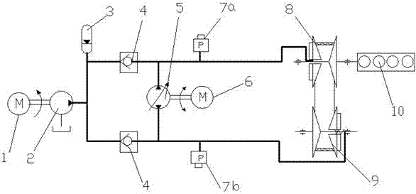
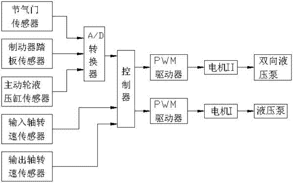
[0020] like figure 1 , 2 As shown, the pump-controlled CVT electro-hydraulic control system includes driving wheel hydraulic cylinder 8, driven wheel hydraulic cylinder 9, speed ratio control hydraulic circuit, clamping force control hydraulic circuit, controller, driving wheel hydraulic cylinder pressure sensor 7a and driven wheel Hydraulic cylinder pressure sensor 7b. The effective areas of the driving wheel hydraulic cylinder 8 and the driven wheel hydraulic cylinder 9 are equal. The speed ratio control hydraulic circuit includes a motor II6 and a two-way hydraulic pump 5, the motor II6 drives the two-way hydraulic pump 5, and the oil ports at both ends of the two-way hydraulic pump 5 communicate with the driving wheel hydraulic cylinder 8 and the driven wheel hydraulic cylinder 9 respectively. The clamping force control hydraulic circuit...


PUM


Abstract

The invention discloses a pump-controlled CVT (continuously variable transmission) electric hydraulic control system, which comprises a driving wheel hydraulic cylinder, a driven wheel hydraulic cylinder, a speed ratio control hydraulic loop, a clamping force control hydraulic loop, a controller and two pressure sensors. Effective areas of the driving wheel hydraulic cylinder and the driven wheel hydraulic cylinder are equal; the speed ratio control hydraulic loop comprises a motor II and a bidirectional hydraulic pump, and oil ports of two ends of the bidirectional hydraulic pump are respectively communicated with the driving wheel hydraulic cylinder and the driven wheel hydraulic cylinder; the clamping force control hydraulic loop comprises a motor I, a hydraulic pump, an energy accumulator and one-way valves; an oil outlet of the hydraulic pump is respectively communicated with the driving wheel hydraulic cylinder and the driven wheel hydraulic cylinder via the two one-way valves; and two pressure sensors are respectively mounted on pipelines communicated with the driving wheel hydraulic cylinder and the driven wheel hydraulic cylinder. The oil inlet port and the oil outlet port of the bidirectional hydraulic pump in the speed ratio control hydraulic loop are respectively communicated with the driving wheel hydraulic cylinder and the driven wheel hydraulic cylinder via pipelines, pressure differences of the inlet port and the outlet port of the bidirectional hydraulic pump is reduced, consumption of power of a speed ratio adjusting hydraulic pump is not high, flow of a pressure control hydraulic pump is quite low, the pressure control hydraulic pump only supplements leakage of the system, and consumed power is lower.

Description

technical field [0001] The invention relates to a belt type continuously variable transmission, in particular to a control system suitable for a metal belt type continuously variable transmission (CVT). Background technique [0002] Continuously Variable Transmission (CVT for short) can continuously change the transmission ratio, so that the engine can run on the best fuel economy curve or the best power curve, and can continuously provide power under the condition of changing speed, which greatly improves the Improve the power of the car, the fuel economy and the comfort of the driver. [0003] The control system of the existing vehicle CVT is mainly based on the valve-controlled electro-hydraulic control system. The hydraulic pump shaft is generally connected with the output shaft of the engine. The power of the hydraulic pump is provided by the engine. As long as the engine starts to work, the hydraulic pump and the entire hydraulic system will start to work. The engine...

Claims


Application Information

Patent Timeline
Patent Type & Authority Patents(China)
IPC IPC(8): F16H61/4008
Inventor 郝建军石晓辉程昶梁晓龙廖江林葛帅帅
Owner CHONGQING ACADEMY OF SCI & TECH
Learn More