Kiln waste heat utilization system

A waste heat and kiln technology, applied in furnaces, waste heat treatment, furnace components, etc., can solve the problems of less frequency of plaster mold grouting per shift, wide distribution of grouting platform heating systems, and unreasonable layout of waste heat pipes, etc., to achieve Overcome the effects of unreasonable cooling, increased use times, and reduced heat intensity

Inactive Publication Date: 2012-06-06
枝江市玖源包装制品有限公司
View PDF0 Cites 3 Cited by
  • Summary
  • Abstract
  • Description
  • Claims
  • Application Information

AI Technical Summary

Problems solved by technology

[0002] During the production process of the roller kiln, the hot air generated carries a large amount of heat energy, the waste heat is not fully utilized, the layout of the waste heat pipeline is unreasonable, and the heating system of the grouting table is widely distributed, resulting in a large heat loss, resulting in a low utilization rate of the overall waste heat , fewer times per shift for plaster mold grouting (twice per shift)
It is difficult to achieve the desired effect in production under the existing heat source

Method used


Image

  • Kiln waste heat utilization system
  • Kiln waste heat utilization system

Examples


Embodiment Construction

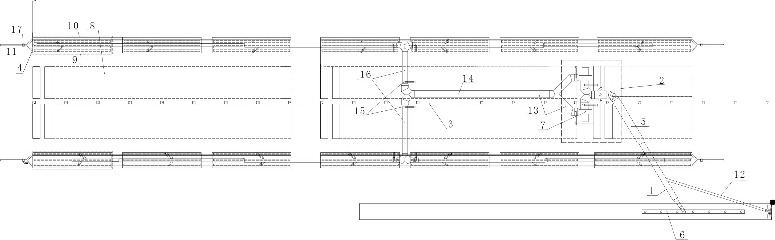
[0019] Such as figure 1 As shown, a kiln waste heat utilization system is composed of a remote heat extraction system 1, a mixing system 2, a conveying system 3 and a moisture removal system 4. One end of the air pipe 5 in the remote heat extraction system 1 is connected to the kiln waste heat extraction air The pipe 6 is connected, the other end of the air pipe 5 is connected with the mixing chamber of the mixing system 2, the mixing chamber is connected with the boiler induced draft fan 7, the air pipe of the mixing chamber is provided with a cold air gate, and the outlet pipe of the boiler induced draft fan 7 passes through the conveying system 3 The conveying pipeline communicates with a plurality of drying chambers. The drying chamber is divided into a mold drying chamber 9 close to the grouting area 8 and a billet drying chamber 10 outside the mold drying chamber 9. The drying chamber communicates with the dehumidification pipe 11 of the dehumidification system 4 .

[00...


PUM


Abstract

The invention relates to a kiln waste heat utilization system, which comprises a remote heat collection system, a mixing system, a conveying system and a dehumidification system. One end of an air pipe in the remote heat collection system is connected with a kiln waste heat collection air pipe, the other end of the air pipe is communicated with a mixing chamber of the mixing system, the mixing chamber is communicated with an induced draft fan of a boiler, an air pipe of the mixing chamber is provided with a cold air gate, the outlet pipe of the induced draft fan of the boiler is communicated with a plurality of drying chambers through a conveying pipe of the conveying system, and the drying chambers are divided into a mold drying chamber close to a grouting area and a blank drying chamber outside the mold drying chamber and are communicated with a dehumidification pipe of the dehumidification system. By adopting the kiln waste heat utilization system, heat in hot air produced by a kiln can be reused for drying blanks and molds produced with the kiln, the waste heat can be effectively utilized, the energy can be saved, and the production yield of the kiln can be improved.

Description

technical field [0001] The invention relates to a waste heat utilization system, in particular to a kiln waste heat utilization system. Background technique [0002] During the production process of the roller kiln, the hot air generated carries a large amount of heat energy, the waste heat is not fully utilized, the layout of the waste heat pipeline is unreasonable, and the heating system of the grouting table is widely distributed, resulting in a large heat loss, resulting in a low utilization rate of the overall waste heat , The frequency of plaster mold grouting per shift is small (twice per shift). It is difficult to achieve the desired effect in production under the existing heat source. Contents of the invention [0003] The technical problem to be solved by the present invention is to provide a kiln waste heat utilization system, which can re-use the heat energy in the hot air produced by the kiln for drying the body and mold produced by the kiln, so that the was...

Claims


Application Information

Patent Timeline
Patent Type & Authority Applications(China)
IPC IPC(8): F27D17/00F26B21/00
CPCY02P10/25
Inventor 刘凤春胡延林赵晓春王金华
Owner 枝江市玖源包装制品有限公司
Why Eureka
Try Eureka