
Termination structure for superconducting cable

一种终端结构、超导电缆的技术,应用在超导电性器件、超导体元素的用法、低温电缆的电缆配件等方向,达到终端结构紧凑、密封效果提高、绝缘薄弱部分减少的效果

Active Publication Date: 2012-05-23
LG CABLE LTD (KR)
View PDF6 Cites 11 Cited by
  • Summary
  • Abstract
  • Description
  • Claims
  • Application Information

AI Technical Summary

Problems solved by technology

Since the cover seal is the weakest part, when an insulation failure occurs in the seal at one of the boundaries, there is the problem of having to replace the entire bushing

Method used


Image

  • Termination structure for superconducting cable
  • Termination structure for superconducting cable
  • Termination structure for superconducting cable

Examples


Embodiment Construction

[0030] Exemplary embodiments are described more fully below with reference to the accompanying drawings that illustrate the exemplary embodiments. This invention may, however, be embodied in many different forms and should not be construed as limited to the exemplary embodiments set forth herein. Rather, these exemplary embodiments are provided so that this disclosure will be thorough and complete, and will fully convey the scope of the disclosure to those skilled in the art. In the description, well-known features and technical details are omitted to avoid unnecessarily obscuring the embodiments of the invention.

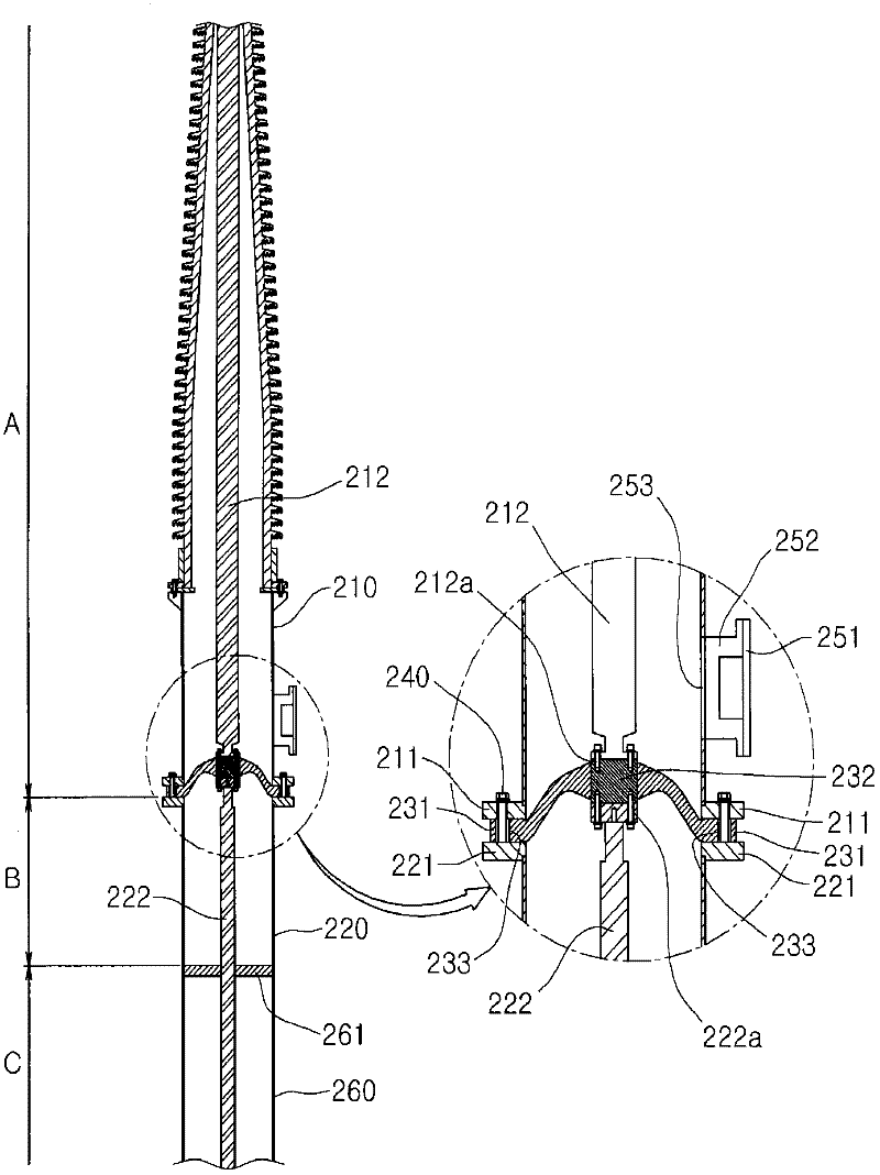
[0031] figure 2 is a sectional view showing a terminal structure according to an embodiment.

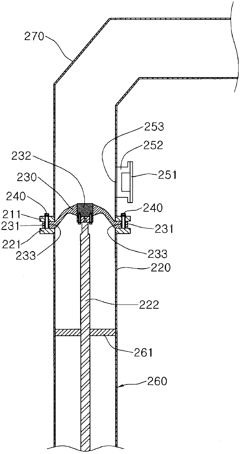
[0032] image 3 is a sectional view illustrating connection of a terminal structure to an external device according to an embodiment.

[0033] As shown in the figure, the detachable terminal structure of the superconducting cable according to the embodiment is divide...


PUM

PropertyMeasurementUnit
diameteraaaaaaaaaa

Abstract

Disclosed is a separable termination structure for a superconducting cable. A termination structure for a superconductor cable according to an embodiment includes: a first tube including a conductive rod therein to form a room temperature section; and a second tube including a conductive rod therein to form a temperature gradient section, wherein the first and second tubes are joined to be separable from each other.

Description

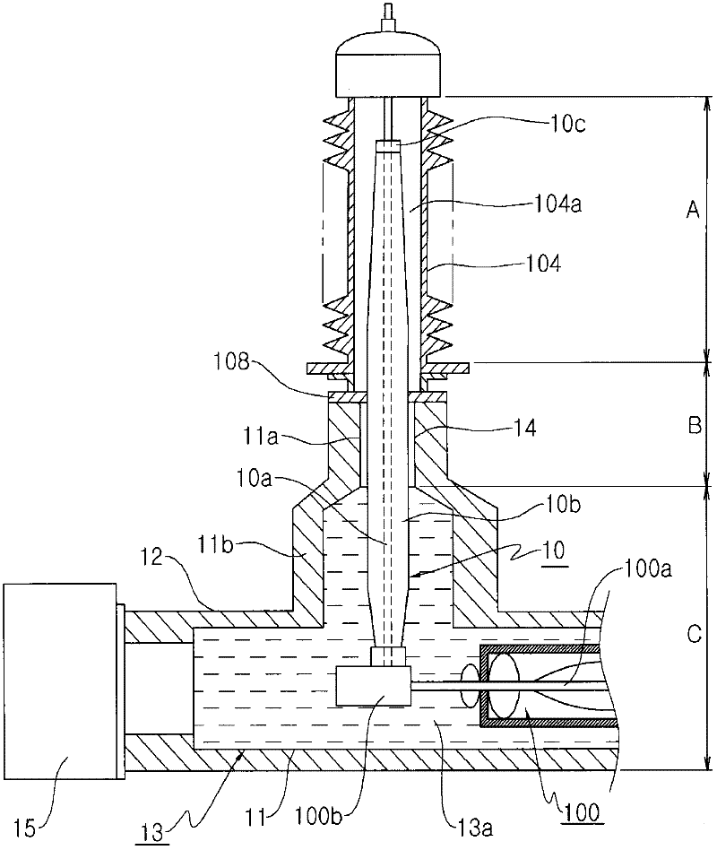
technical field [0001] The present invention relates to a terminal structure of a superconducting cable, and more particularly, to a terminal structure of a superconducting cable in which the terminal of the superconducting cable is moved from the very low temperature side to the room temperature side. Background technique [0002] The terminal structure of the existing superconducting cable has the terminal structure disclosed in Korean Laid-Open Patent No. 10-2007-102651. Refer below figure 1 To describe the existing terminal structure for superconductivity. [0003] see figure 1 , the terminal structure of the existing superconducting cable includes: the terminal of the superconducting cable 100; the refrigerant container 11 at the terminal; the vacuum container 12 covering the outer periphery of the refrigerant container 11 ; and the porcelain tube 104 protruding from and connected to the room temperature side of the vacuum container 12 . [0004] The porcelain tube ...

Claims


Application Information

Patent Timeline
Patent Type & Authority Applications(China)
IPC IPC(8): H02G15/22H01B12/02
CPCY02E40/648H02G15/34Y02E40/60H01B12/02H02G15/22
Inventor 崔彰烈李秀吉金春东张铉万张锡宪成许庆
Owner LG CABLE LTD (KR)
Learn More