Measuring system for resonant frequency measurement on disc brake pads

A disc brake pad and resonant frequency technology, applied in the field of measurement systems, can solve problems such as insufficient non-contact microphone measurement, and achieve the effects of stable measurement, avoiding node lines, and high precision

Inactive Publication Date: 2012-05-09
FEDERAL MOGUL BREMSBELAG
View PDF5 Cites 0 Cited by
  • Summary
  • Abstract
  • Description
  • Claims
  • Application Information

AI Technical Summary

Problems solved by technology

[0009] The non-contact microphone measurements known in the prior art are insufficient and only a limited recording can be made when using a microphone

Method used


Image

  • Measuring system for resonant frequency measurement on disc brake pads
  • Measuring system for resonant frequency measurement on disc brake pads

Examples


Embodiment Construction

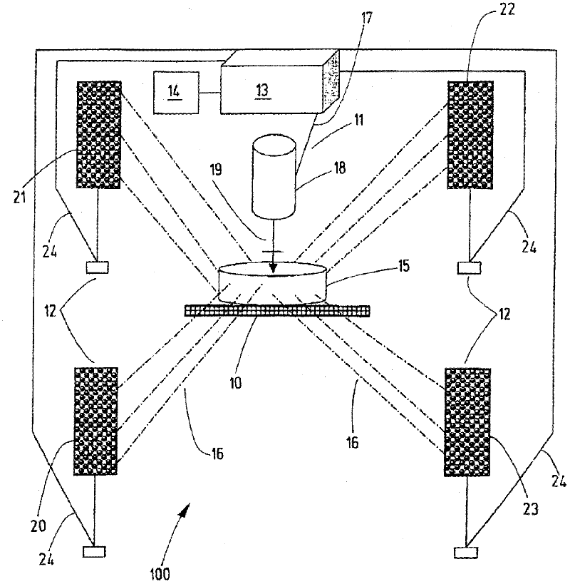
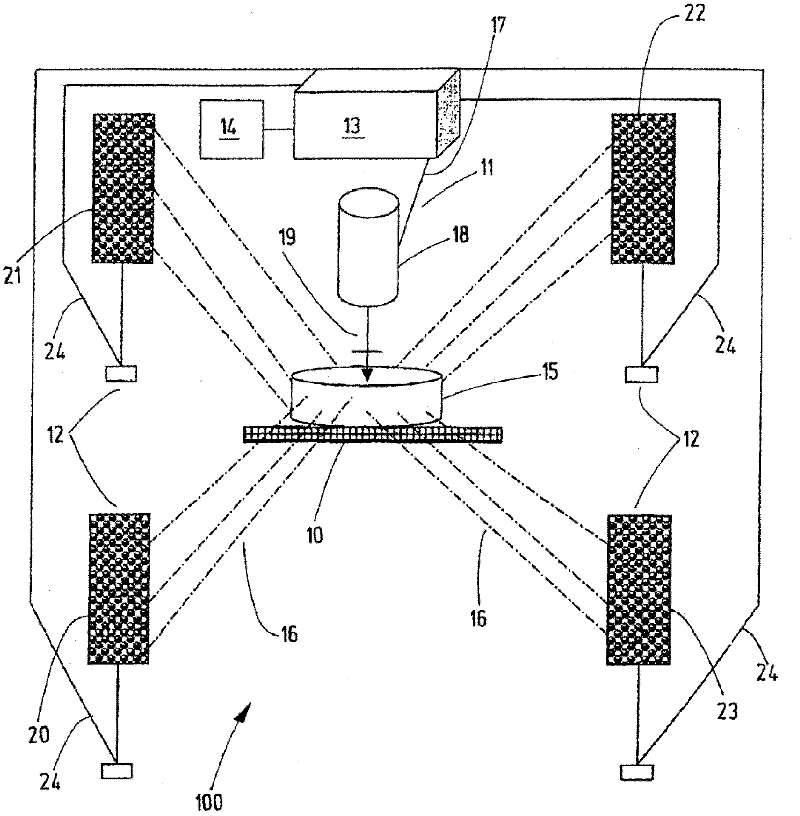
[0039] exist figure 1 In , the measuring system according to the invention is shown marked with 100 .

[0040] The measurement system 100 is used to measure the resonant frequency of the disc brake pad.

[0041] figure 1 The illustrated measurement system 100 basically includes two elements. The first element is the measuring device, comprising the object holder 10 , the impulse stimulation device 11 and the sensor system 12 . The second element is a data recording device 13 comprising a measurement computer, a frequency analyzer and a computer unit marked 14 .

[0042] The object carrier 10 is made of plastic foam in the form of a base, on which the disc brake pads 15 are attached at defined positions. The plastic foam thus serves to support the disc brake pads and acts as sound insulation for the object. Above the disc brake pad 15, that is, on the other side of the object support 10 of the disc brake pad 15, a pulse stimulation device 11 is installed, figure 1 In the ...


PUM

PropertyMeasurementUnit
Densityaaaaaaaaaa
Densityaaaaaaaaaa

Abstract

A system (100)is provided for measuring the resonant frequencies on disc brake pads (15). The system (100)includes a data recording apparatus (13)and a measuring device in the form of a sensor system (12). In order to record a maximum number of resonant frequencies, the sensor system (12)consists of two or more microphones (20, 21, 22, 23).

Description

technical field [0001] The invention relates to a measuring system for measuring resonance frequencies on disc brake pads, comprising a data recording device and a measuring device with a sensor system. [0002] Furthermore, the invention relates to a method for measuring resonance frequencies on disc brake pads using a microphone. Background technique [0003] Measuring systems of the type mentioned at the outset are generally known and familiar to those skilled in the art. [0004] The resonance frequency is an important characteristic variable for describing the vibration behavior of a disc brake pad. Variables that affect the resonant frequency, i.e. the vibratory behavior of a disc brake pad, include, for example, elasticity, compressibility, density, mass, porosity, hardness, thickness, geometry (e.g. disc brake pad sheet chamfer), and damping characteristics. [0005] When examining disc brake pads, for example if the disc brake pads have approximately the same ove...

Claims


Application Information

Patent Timeline
IPC IPC(8): G01M13/00G01N29/12G01N3/32
CPCG01N29/045G01N29/14G01N2291/2696G01N2291/014
Inventor 鲍里斯·沃尼兹
Owner FEDERAL MOGUL BREMSBELAG
Why Eureka
Try Eureka