Eureka AIR delivers breakthrough ideas for toughest innovation challenges, trusted by R&D personnel around the world.

Multi-point injection gas supply system for fuel gas generator set

A technology of generator set and gas supply system, applied in combustion engine, internal combustion piston engine, engine control and other directions, can solve the problems of large gas volume, waste, environmental pollution of harmful exhaust gas, etc., and achieve the effect of saving cost and saving gas consumption

Inactive Publication Date: 2012-05-09
崔敏娟
View PDF0 Cites 1 Cited by
  • Summary
  • Abstract
  • Description
  • Claims
  • Application Information

AI Technical Summary

Problems solved by technology

[0002] The current multi-point injection system is equipped with a fuel injector in each cylinder. The electronic control unit controls and injects each cylinder individually or in groups in order to make the gas distribution even. The intake pipe is generally designed according to the maximum gas volume. It directly controls the air-fuel ratio. Therefore, whether the engine is in a cold state or a hot state, its transient response and fuel economy are excellent. However, the control system of the above-mentioned multi-point injection system is more complicated, the cost is higher, and it cannot be realized. The gas volume is automatically and reasonably controlled, and the intake pipe is designed according to the maximum gas volume. When the gas combustion is not complete, it will cause energy waste, especially for gas generator sets, which have a large gas volume and cause even greater waste. And the harmful waste gas produced by the incomplete combustion of gas will cause serious pollution to the environment

Method used


Image

  • Multi-point injection gas supply system for fuel gas generator set
  • Multi-point injection gas supply system for fuel gas generator set

Examples


Embodiment Construction

[0013] Below in conjunction with accompanying drawing, further illustrate the present invention through embodiment.

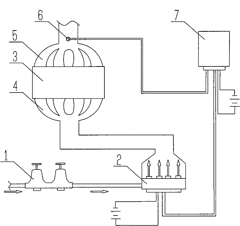
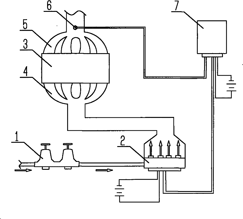
[0014] Such as figure 1 As shown, the multi-point injection gas supply system of the gas generator set according to the present invention includes a pressure reducing valve 1, a gas injection rail 2, a cylinder 3, an intake manifold 4, and an exhaust manifold 5, and the exhaust manifold 5 is provided with a wide-area oxygen sensor 6, and both the wide-area oxygen sensor 6 and the gas injection rail 2 are connected to a computer 7.

[0015] The gas enters the gas injection rail 2 after being decompressed by the pressure reducing valve 1, and enters the cylinder 3 through the intake manifold 3 according to the theoretical air-fuel ratio preset by the computer 7, and after burning in the cylinder 3, the exhaust gas generated At the same time, the wide-area oxygen sensor 6 detects the concentration of harmful substances at the exhaust gas channel, and sends the de...


PUM


Abstract

The invention discloses a multi-point injection gas supply system for a fuel gas generator set. The multi-point injection gas supply system comprises a decompression valve, a fuel gas injection track, a cylinder, a gas inlet manifold and a gas outlet manifold, wherein the gas outlet manifold is provided with an oxygen sensor; and both the oxygen sensor and the fuel gas spray track are connected with a signal processing and controlling device. In the invention, the practically-required air-fuel ratio is optimized automatically by using the signal processing and controlling device, the startup time of the fuel gas injection track is adjusted automatically according to a signal detected by the oxygen sensor, and the air-fuel ratio practically required by the cylinder of the generator set is optimized, so that the quantity of harmful substances emitted by tail gas are controlled at the minimum value, energy is saved, and contribution to environmental protection is made simultaneously.

Description

technical field [0001] The invention relates to a multi-point injection air supply system, in particular to an energy-saving and environment-friendly multi-point injection air supply system for a gas generator set that automatically adjusts the air-fuel ratio. Background technique [0002] The current multi-point injection system is equipped with a fuel injector in each cylinder. The electronic control unit controls and injects each cylinder individually or in groups in order to make the gas distribution even. The intake pipe is generally designed according to the maximum gas volume. It directly controls the air-fuel ratio. Therefore, whether the engine is in a cold state or a hot state, its transient response and fuel economy are excellent. However, the control system of the above-mentioned multi-point injection system is more complicated, the cost is higher, and it cannot be realized. The gas volume is automatically and reasonably controlled, and the intake pipe is designe...

Claims


Application Information

Patent Timeline
Patent Type & Authority Applications(China)
IPC IPC(8): F02D19/02F02B63/04
CPCY02T10/32Y02T10/30
Inventor 崔敏娟
Owner 崔敏娟
Why Eureka
Eureka Blog
Learn More