
Large-torque cone-hypocycloid speed reducer of rotary brush aeration machine

An aerator and high-torque technology, applied in water aeration, chemical instruments and methods, sustainable biological treatment, etc., can solve the difficulty of on-site inspection of oil quantity in the case of hard-toothed reducer, poor lubrication of bearings, service life Short and other problems, to achieve the effect of simple structure, improved bending ability and short axial dimension

Active Publication Date: 2012-05-09
JIANGSU TAILONG MACHINERY GRP CO CO LTD
View PDF6 Cites 2 Cited by
  • Summary
  • Abstract
  • Description
  • Claims
  • Application Information

AI Technical Summary

Problems solved by technology

[0004] (1) Short service life: In actual use, only a few months of high-speed bevel gear bearing breakage and bevel tooth breakage, the reason is that the high-speed bevel gear is located at the highest point, and the lubricating oil splashed by the low-speed gear is not enough to lubricate the bearing. Poor lubrication makes the bearing thirsty for oil early, causing the cage to break, and the scattered rollers (steel balls) cause the bevel gear to break teeth;
[0005] (2) It is difficult to check the oil quantity in the case of the K series hard tooth surface reducer on site, and it is very inconvenient to refuel;
[0006](3) "Bevel gear + parallel shaft" hard tooth surface reducer is a domestic imitation of SEW company's product, so the price is too high

Method used


Image

  • Large-torque cone-hypocycloid speed reducer of rotary brush aeration machine

Examples


Embodiment Construction

[0021] The present invention is described in detail below in conjunction with accompanying drawing:

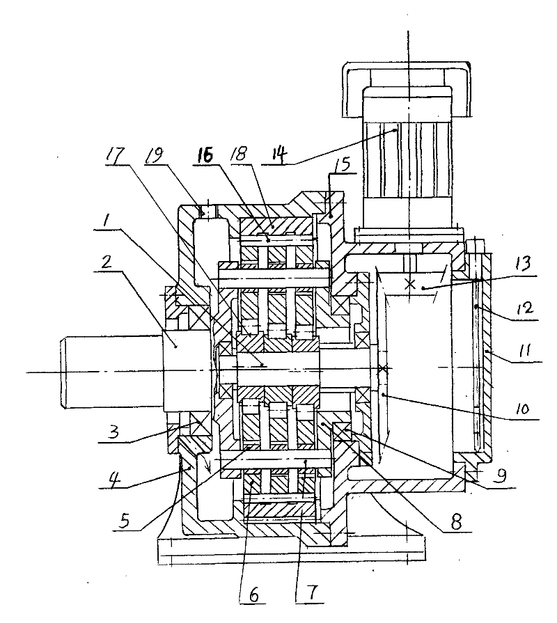
[0022] refer to figure 1 .A high-torque cone-pendulum reducer for a brush-type aerator, characterized in that it consists of a bevel gear pair installed in a small machine base (15) and a cycloid transmission member installed in a machine base (4) , the small frame (15) is connected to the end face of the frame (4), wherein:

[0023] (A) The bevel gear pair consists of a small bevel gear shaft (13) mounted on the small machine base (15) and a large bevel gear (10) connected to the output and extension end of the input shaft (1), and the small bevel gear shaft is connected to the motor ( 14);

[0024] (B) The cycloidal transmission includes an input shaft (1), an output shaft (2), three cycloidal wheels (6) whose phase angles are staggered by 120°, pin-toothed pins (16), three eccentric bearings (17), Composed of pin gear housing (18) and W output mechanism, the pin gear hou...


PUM


Abstract

The invention relates to the technical field of speed reduction of aeration machines, in particular to a large-torque cone-hypocycloid speed reducer of a rotary brush aeration machine. The large-torque cone-hypocycloid speed reducer is characterized by comprising a bevel gear pair and a hypocycloid drive, wherein the bevel gear pair comprises a drive bevel gear and a driven bevel gear; the hypocycloid drive comprises a pin wheel housing, a needle pin, three cycloidal wheels and a W output mechanism, wherein a screw hole with a ventilation cap is formed on an engine base, an oil return hole isarranged in a bearing hole of the engine base, the oil return hole is located below a space between an oil seal and a bearing, the pin wheel housing is connected to an inner hole of the engine base, an oil feeding hole is arranged in a round end cover on the small end face of the engine base, an oil scale is arranged in the hole, and the oil scale is drawn to check the oil quantity and refuel rapidly. The large-torque cone-hypocycloid speed reducer of the rotary brush aeration machine has the advantages that: (a) hypocycloid wheel teeth are continuous, so that the overload capacity is larger than external gearing transmission of a parallel shaft, and bearing capacities of three bearings can be increased by 50 percent; (b) the price of the hypocycloid speed reducer is less than one third of a hard tooth surface, so that the cost is 50-55% lower than that of the hard tooth surface; and (c) the oil quantity in the speed reducer can be rapidly checked and the oil can be rapidly refueled to the speed reducer in both dirty and exposed environments.

Description

【Technical field】 [0001] The invention relates to the technical field of deceleration of aerators, and relates to a high-torque cone-pendulum reducer for a rotary brush aerator. 【Background technique】 [0002] The rotary brush aerator is widely used in the treatment of urban domestic sewage and industrial wastewater in petroleum, chemical, leather, printing and dyeing, papermaking, food, gas and other industries. The environment in which the aerators are used is quite harsh. There are many aerators in operation in a large open-air sewage treatment plant. It is cold in winter and hot and smelly in summer. No one of the workers wants to stay for a few minutes longer. The rotary brush aerator is mainly composed of two parts: the rotary brush and the reducer. Among them, the SEW-like K series bevel gear + helical hard tooth surface reducer has the highest failure rate. [0003] This is because the background technology K series hard tooth surface reducer has the following probl...

Claims


Application Information

Patent Timeline
Patent Type & Authority Applications(China)
IPC IPC(8): C02F7/00C02F3/02C02F3/30C02F1/74
CPCY02W10/10
Inventor 吴声震
Owner JIANGSU TAILONG MACHINERY GRP CO CO LTD
Learn More