Proximity switch

A technology of proximity switch and switch amplification, applied in the field of switches, can solve problems such as increasing the use cost, reducing the reliability of the proximity switch, and transistor damage.

Inactive Publication Date: 2012-04-11
浙江正泰机床电气制造有限公司
View PDF4 Cites 4 Cited by
  • Summary
  • Abstract
  • Description
  • Claims
  • Application Information

AI Technical Summary

Problems solved by technology

[0003] Although this structure can effectively reflect the existence of metal objects, it does not have the overcurrent protection function of the switch-on delay protection box. In actual use, there are often malfunctions of the proximity switch at the moment of switch-on, or work under short-circuit or over-current conditions. It will cause damage to the transistor, reduce the reliability of the proximity switch, and increase the cost of use

Method used


Image

  • Proximity switch
  • Proximity switch
  • Proximity switch

Examples


Embodiment Construction

[0012] Below in conjunction with accompanying drawing, the present invention will be further described:

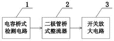
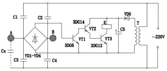
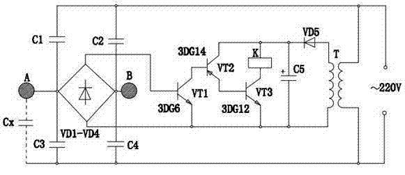
[0013] The proximity switch is composed of a capacitive bridge detection circuit 1, a diode bridge rectifier 2 and a switch amplifier circuit 3 that are connected in coordination. The capacitive bridge detection circuit 1 is composed of capacitors C1-C4. The rectifier 2 is composed of diodes VD1-VD4, the switch amplifier circuit 3 is composed of transistors VT1-VT3, Zener diode VD5, capacitor C5 and relay K, transistor VT1 adopts 3DG6, transistor VT2 adopts 3DG14, transistor VT3 adopts 3DG12; capacitor bridge detection The input end of the circuit 1 is connected with the 220V mains, and its output end is connected with the input end of the diode bridge rectifier 2, and the output end of the diode bridge rectifier 2 is connected with the switching amplifier circuit 3; the input end of the diode bridge rectifier 2 is Metal sheet A and metal sheet B are respectively connected...


PUM


Abstract

The invention relates to a switch, in particular to a proximity switch. The proximity switch is characterized by consisting of a capacitance bridge detection circuit, a diode bridge rectifier and a switch amplifying circuit which are connected in a matching way, wherein the capacitance bridge detection circuit consists of capacitors C1-C4; the diode bridge rectifier consists of diodes VD1-VD4; the switch amplifying circuit consists of transistors VT1-VT3, a voltage stabilizing diode VD5, a capacitor C5 and a relay K; the input end of the capacitance bridge detection circuit is connected with 220V commercial power, and the output end of the capacitance bridge detection circuit is connected with the input end of the diode bridge rectifier; the output end of the diode bridge rectifier is connected with the switch amplifying circuit; and the two ends of the input end of the diode bridge rectifier are connected with a metal sheet A and a metal sheet B respectively. The proximity switch can be used be applied to burglary prevention alarm, automatic notification, automatic protection and the like, runs stably, is prevented from being interfered easily and performing error actions, and has low production cost.

Description

technical field [0001] The invention relates to a switch, in particular to a proximity switch. Background technique [0002] There are many kinds of existing proximity switches, and the common ones are inductive proximity switches, inductive proximity switches, and ultrasonic proximity switches. The inductive proximity switch is composed of an LC high-frequency oscillator and an amplification processing circuit. When a metal object approaches the oscillating induction head that can generate an electromagnetic field, an eddy current is generated inside the metal object. This eddy current reacts on the high-frequency oscillator to attenuate the oscillation ability of the high-frequency oscillator, and the parameters of the internal circuit change, thereby identifying whether there is a metal object approaching, and then controlling the ON or end of the switch. The objects that this proximity switch can detect must be metal objects. [0003] Although this structure can effect...

Claims


Application Information

Patent Timeline
Patent Type & Authority Applications(China)
IPC IPC(8): H03K17/955
Inventor 戴隆党
Owner 浙江正泰机床电气制造有限公司
Why Eureka
Try Eureka