
Double-layer steel-truss concrete laminated arch structure and construction method thereof

A technology of concrete structure and arch structure, which is applied to arch bridges, bridge parts, erection/assembly bridges, etc. It can solve the problems of long construction period, self-heavy arch ribs, and difficult construction, and achieve the effect of simple and reasonable structural stress

Inactive Publication Date: 2012-04-11
ZHONGTIE MAJOR BRIDGE RECONNAISSANCE & DESIGN INST +1
View PDF6 Cites 8 Cited by
  • Summary
  • Abstract
  • Description
  • Claims
  • Application Information

AI Technical Summary

Problems solved by technology

Concrete arch bridges have the following disadvantages: a. The heavy weight of the arch ribs is the main factor restricting the span of concrete arch bridges; b. The construction is difficult and the construction period is long
Concrete-filled steel tube arch bridges combine the advantages of steel arch bridges and ordinary reinforced concrete arch bridges, and each takes advantage of the material properties of the two materials. The disadvantage is that due to the shrinkage and deformation of the concrete in the tube, it is separated from the steel tube and cannot form an overall structure.

Method used


Image

  • Double-layer steel-truss concrete laminated arch structure and construction method thereof
  • Double-layer steel-truss concrete laminated arch structure and construction method thereof
  • Double-layer steel-truss concrete laminated arch structure and construction method thereof

Examples


Embodiment Construction

[0016] Embodiments of the present invention will be further described below in conjunction with the accompanying drawings.

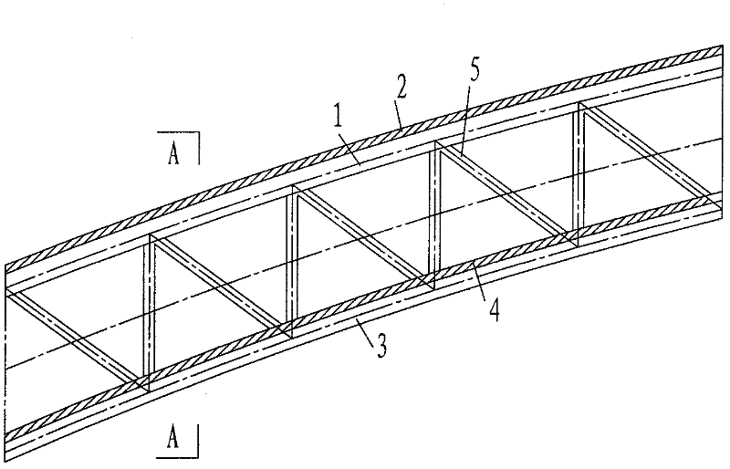
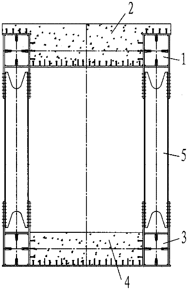
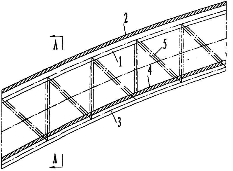
[0017] refer to figure 1 , 2 , the double-layer steel truss concrete composite arch structure of the present invention is to have an upper steel structure 1 and an upper concrete structure 2 above the steel truss arch formed by steel webs, rods 5 and steel chords, and a lower steel structure below 3 and the lower concrete structure 4.

[0018] For the construction method of the double-layer steel truss concrete composite arch structure, the specific steps for the arch form cast on site are as follows:

[0019] 1) Steel webs, rods 5 and steel chords are used to form a steel truss arch, and the steel truss arch structure is not only a part of the permanent structure, but also a formwork for the post-cast concrete structure;

[0020] 2) Concrete is poured on the upper and lower floors of the steel truss arch structure respectively to form a double-layer ...


PUM


Abstract

The invention relates to a double-layer steel-truss concrete laminated arch structure and a construction method thereof. The structure is characterized in that the upper surface and the lower surface of a steel-truss arch frame consisting of steel web plates, rods and steel chords are provided with an upper-layer steel structure, a lower-layer steel structure, an upper-layer concrete structure and a lower-layer concrete structure. The construction adopts a form of cast in place or prefabricated installation. The cast-in-place construction comprises the following steps: an arch is firstly formed according to a steel structure, and concrete is cast on the arch so as to form the double-layer steel-truss concrete laminated arch structure and realize joint stressing. The prefabricated installation construction comprises the following steps: a laminated structure is firstly formed on the steel structure and the concrete structure in place or in a factory to realize joint stressing, and then the double-layer steel-truss concrete laminated arch structure is formed by in-place installation. In the invention, the advantages are combined on the basis of the traditional concrete arch and the steel-truss arch structure so as to form the double-layer steel-truss concrete laminated arch structure, so that the characteristics of the two materials are fully performed, the used amount of the materials is saved, the structure stressing is simple and reasonable, the construction is convenient, the construction period is shortened, and the requirements for various-span arch bridges can be better met.

Description

technical field [0001] The invention belongs to the field of bridge construction engineering and relates to a cable-stayed bridge with a new structure and a construction method thereof. Background technique [0002] At present, the structural forms of long-span arch bridges in China mainly include the following forms: (1) Steel arch bridges, including steel box arches, steel truss arches, steel pipe arches, etc.; (2) Concrete arch bridges, including concrete box arches, concrete ribbed arches, and concrete trusses (3) The concrete-filled steel tube arch bridge has a large spanning capacity, but the amount of steel used is far greater than that of the other two structural forms, and the project cost is high. Concrete arch bridges have the following disadvantages: a. The arch ribs have a large self-weight, which is the main factor restricting the span of concrete arch bridges; b. The construction is difficult and the construction period is long. Concrete-filled steel tube arc...

Claims


Application Information

Patent Timeline
IPC IPC(8): E01D4/00E01D19/00E01D21/00
Inventor 高宗余梅新咏王碧波苏杨王乐冰
Owner ZHONGTIE MAJOR BRIDGE RECONNAISSANCE & DESIGN INST
Learn More