Wave-surface shaft device and use method

A shaft device and wave surface shaft technology, applied in the field of mechanical shafts, can solve the problems of accelerating oil drainage, scrapping the engine, and high rotation speed, and achieve the effect of reducing wear and increasing the contact area.

Inactive Publication Date: 2012-03-28
纪云龙
View PDF5 Cites 3 Cited by
  • Summary
  • Abstract
  • Description
  • Claims
  • Application Information

AI Technical Summary

Problems solved by technology

[0002] The existing engine crankshaft and gland type camshaft have a smooth cylindrical surface. When they are working, they are lubricated by lubricating oil and the pressure formed by the lubricating oil. Although this lubricating method can ensure that the machine parts Normal use, however, due to the high speed of the working environment, the load is also large
[0003] For example: the tension of the pressure plate of the 430 is between 750 kg and 800 kg. Due to the excessive tension, the side of the thrust pad will be worn out early, and the other side of the thrust pad will be removed from the body due to the large gap. Falling off, traditional linear lubrication, the side of the thrust pad that is stressed cannot get sufficient lubrication because the gap is too small, and the other side will speed up the drainage of engine oil because the gap is too large, etc.
Once this happens, the four supporting connecting rods of the crankshaft body, etc. will all be damaged due to wear and tear, causing the engine to be scrapped.
Now the self-adjusting clutch sub-cylinder has been exerting force backwards, and the strength is about 10 kg. Due to the force being exerted backwards, the crankshaft has been rubbing against the thrust pad when it is running. Due to the temperature rise of the friction thrust pad, the oil film is unevenly distributed. Long-term use will still bring certain wear to the thrust pad, shaft and bearing pad, shortening the service life of the thrust pad, shaft and bearing pad

Method used


Image

  • Wave-surface shaft device and use method
  • Wave-surface shaft device and use method
  • Wave-surface shaft device and use method

Examples


Embodiment Construction

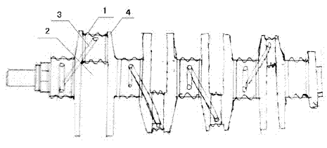
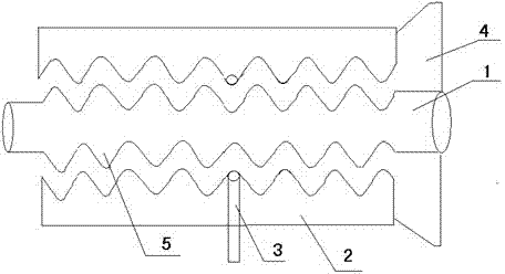
[0014] combined with Figure 1-2 , to further describe the present invention:

[0015] The present invention is mainly composed of a wave surface shaft 1 and a bearing bush 2. The wave surface shaft is composed of a shaft main body and a wave structure. The outer side of the shaft main body is set as a wave structure 5. The wave structure is used in conjunction with the wave structure on the bearing bush. The middle section of the bearing pad is provided with a lubricating oil inlet passage 3, and the lubricating oil moves and lubricates in the gap between the wave surface shaft and the bearing pad.

[0016] Thrust plates 4 are provided at both ends of the above-mentioned wave surface shaft.

[0017] A method for using a wave surface shaft device, comprising the following steps:

[0018] (1) Lubricating oil enters the wave structure through the lubricating oil inlet passage in the middle section of the bearing bush, moves to both ends of the wave surface shaft through th...


PUM


Abstract

The invention relates to a mechanical shaft and a use method, in particular to an engine crankshaft, a wave-surface shaft device of a gland-type camshaft, and use methods, and adopts the technical scheme that the wave-surface shaft device comprises a wave-surface shaft and a bearing bush; the wave-surface shaft comprises a shaft main body and a wave structure; the wave structure is arranged on the outer side of the shaft main body and is used in matching with a wave structure on the bearing bush; a lubricant inlet passage is arranged on the middle section of the bearing bush; and lubricant moves in the clearance between the wave-surface shaft and the bearing bush to serve the lubrication function. The invention has the benefits that the shaft with the wave structure is adopted, so that lubricant can lubricate the shaft in all directions; and opposite acting force is exerted on the wave-surface shaft through resistance force generated through the enlarging of oil pressure, so as to drive the wave-surface shaft to move in an opposite direction, and reduce the abrasion on the bearing bush as well as on thrust plates at two ends of the wave-surface shaft. Therefore, zero abrasion is realized in the real sense.

Description

Technical field: [0001] The invention relates to a mechanical shaft and a use method thereof, in particular to a wave surface shaft device of an engine crankshaft and a gland type camshaft and a use method thereof. Background technique: [0002] The existing engine crankshaft and gland type camshaft have a smooth cylindrical surface. When they are working, they are lubricated by lubricating oil and the pressure formed by the lubricating oil. Although this lubricating method can ensure that the machine parts In normal use, however, due to the high speed of the working environment, the load is also large. [0003] For example: the tension of the pressure plate of the 430 is between 750 kg and 800 kg. Due to the excessive tension, the side of the thrust pad will be worn out early, and the other side of the thrust pad will be removed from the body due to the large gap. Falling, traditional linear lubrication, the side of the thrust pad that is stressed cannot get sufficient ...

Claims


Application Information

Patent Timeline
Patent Type & Authority Applications(China)
IPC IPC(8): F16C35/10F16C3/02F16N1/00
Inventor 纪云龙
Owner 纪云龙
Why Eureka
Try Eureka