
Guide centering adjustment device

A technology for centering adjustment and guide, applied in the field of rolling equipment, can solve the problems of guide and guide traverse centering deviation, unsatisfactory guide and guide centering rate, batch quality accidents, etc., so as to avoid centering errors and reduce guide and guard. Consumption, the effect of reducing sticking to steel

Active Publication Date: 2012-02-22
HEFEI BAISHENG SCI & TECH
View PDF5 Cites 4 Cited by
  • Summary
  • Abstract
  • Description
  • Claims
  • Application Information

AI Technical Summary

Problems solved by technology

The movable crossbeam is commonly used now, and the crossbeam itself has the function of traversing relative to the frame, so as to solve the problem of the centering deviation of the guide in traversing; however, when the above structure is applied to the multi-wire slitting and rolling process , often depending on the number of cutting lines, a corresponding number of guides are set on a beam to guide them into the entrances of the corresponding rolled product racks. Since the guides are respectively directly fastened to the beam, The positional relationship between it and the crossbeam is constant, and the cut semi-finished rolling piece pulled out from the grooving in the previous process, its overall passing path is actually an expanded beam shape from the cutting blade to the entrance of the rolled product stand. , that is to say, each passing path of multiple semi-finished rolled pieces is at a certain angle to the ideal path, and the existing one only relies on the relative movement of the beam to realize the translational centering operation of the guide. Due to the production assembly The existence of errors often makes it difficult to solve the problem of the deflection angle between the actual passing path of the rolled piece and the guiding path of the guide, resulting in the unsatisfactory actual centering rate of the guide, which leads to inevitable contact between the guide and the rolled piece. It is very easy to produce the phenomenon of steel sticking, that is, the "welding" between the iron oxide scale and the alloy guide, and the oxide scale on the guide is bonded, which in turn scratches the rolled piece, causing a vicious circle and easily causing batch quality accidents

Method used


Image

  • Guide centering adjustment device
  • Guide centering adjustment device
  • Guide centering adjustment device

Examples


Embodiment Construction

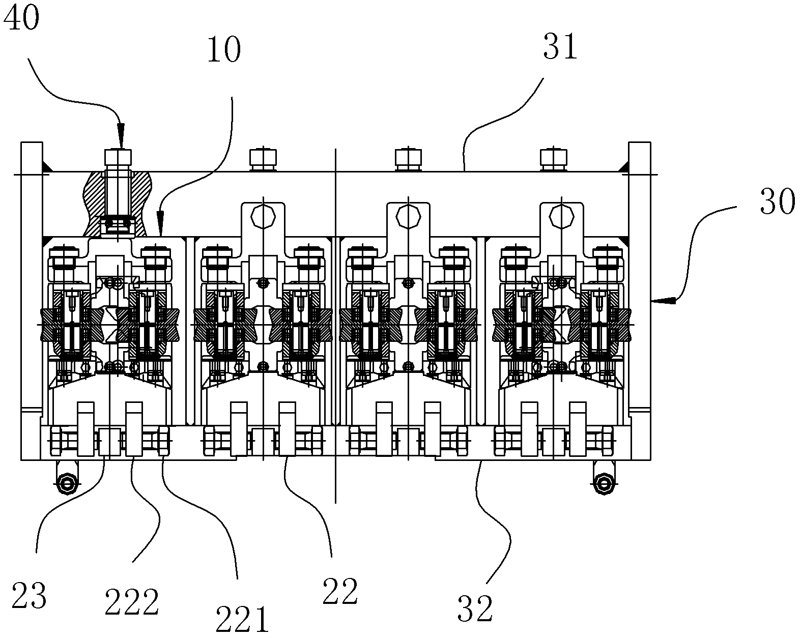
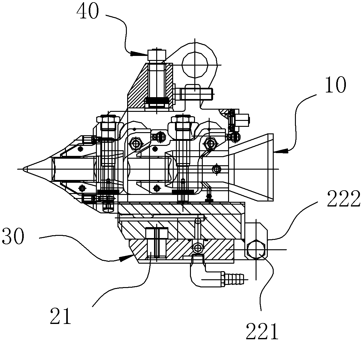
[0009] A centering adjustment device for a guide, comprising a guide body 10 and a base for fixing the guide body 10, the guide body 10 is in conflict with the base, and the centering adjustment device for the guide also includes The adjustment mechanism used to drive the guide body 10 to swing along the mating surface of the base, the swing axis of the adjustment mechanism is located on the passing path of the rolled piece, such as Figure 2-3 shown.

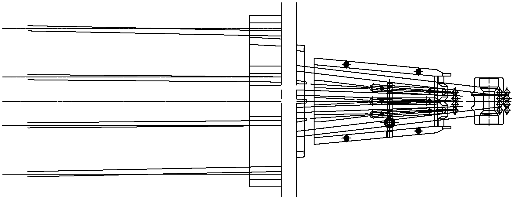
[0010] Such as figure 1 It can be seen from the figure that the actual path of the rolled piece is moving in the split rolling, that is to say, the guide adjustment in its practical application is not suitable for the ordinary translational guide adjustment method with movable beams; due to many Each passing path of a semi-finished rolled piece forms a certain angle with the ideal path, and the deviations of the angles are often different. The lateral movement adjustment of the beam along the frame of the movable beam must not...


PUM


Abstract

The invention belongs to the field of steel rolling machinery, and particularly relates to a guide centering adjustment device at an entrance of a multi-line splitting rolling product rack. The device comprises a guide body and a base for fixing the guide body, wherein the guide body and the base are in surface contact and fit; the guide centering adjustment device also comprises a regulation mechanism for driving the guide body to swing along the fitting surface of the base; and the swing axle center of the regulation mechanism is located on the traveling path of the rolling piece. The equipment provided by the invention has a simple structure, and realizes accurate positioning; and through the equipment, the problem in the deflection angle between the actual traveling path of the rolling piece and the guiding path of the guide is solved, thus the steel adhesion in the splitting rolling process is effectively reduced, the product quality is improved, the production efficiency is improved, the guide consumption is reduced, and the equipment is suitable for practical splitting rolling production.

Description

technical field [0001] The invention belongs to the field of steel rolling equipment, and in particular relates to a centering adjustment device for guides and guards used at the entrance of a machine frame for multi-line cutting and rolling products. Background technique [0002] Guides play an important role in slitting and rolling production, and in a certain sense, they are the continuation of slitting and exporting. Usually, when the guide is installed, it is fixed to the beam by installing the base, and the beam is fixed on the frame. The movable crossbeam is commonly used now, and the crossbeam itself has the function of traversing relative to the frame, so as to solve the problem of the centering deviation of the guide in traversing; however, when the above structure is applied to the multi-wire slitting and rolling process , often depending on the number of cutting lines, a corresponding number of guides are set on a beam to guide them into the entrances of the cor...

Claims


Application Information

Patent Timeline
IPC IPC(8): B21B39/14
Inventor 娄霆李运强刘成斌季幼平
Owner HEFEI BAISHENG SCI & TECH
Learn More